270
Network Protocol Reference Section B-3
The data set in the response is as follows:
When the Read Holding Register command cannot be executed normally,
refer to the exception response.
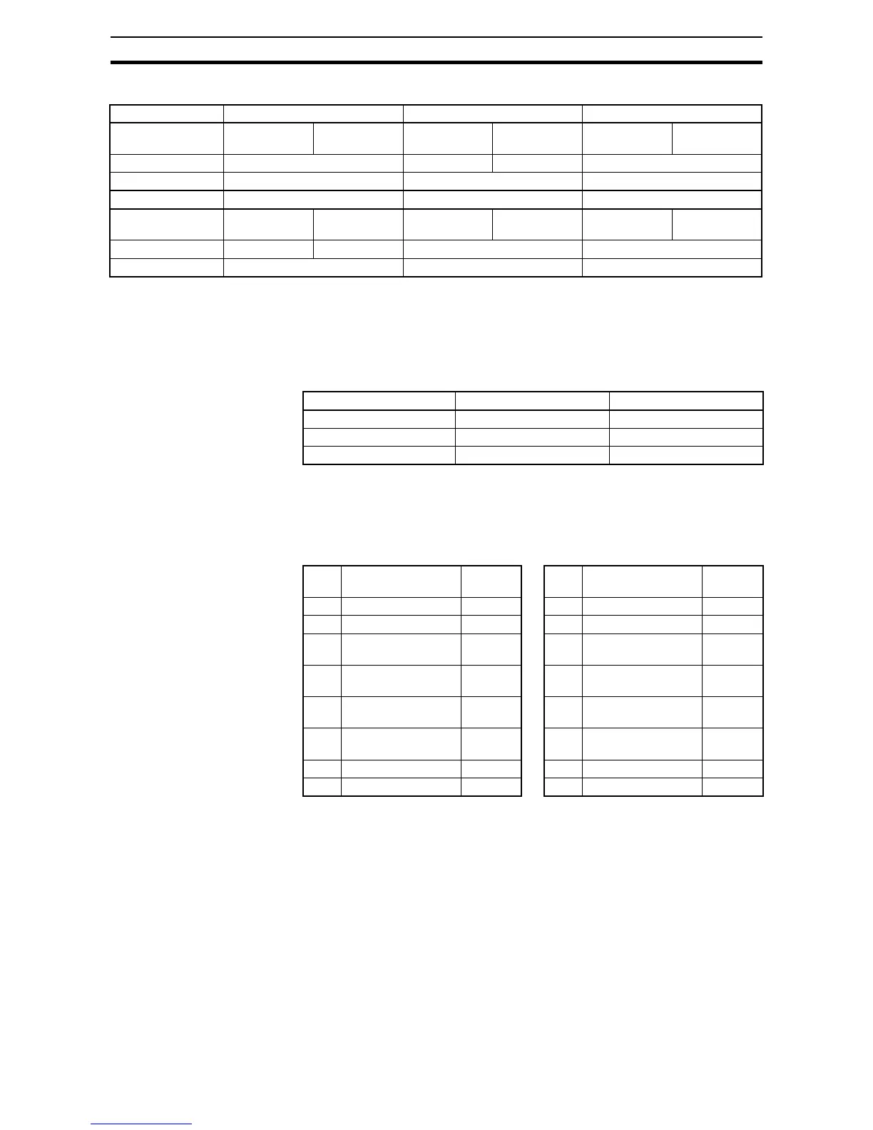
Write in Coil [05h]:
This function writes data in a single coil. Coil status changes are as follows:
An example follows (note that to command the inverter, set A002=03):
• Sending a RUN command to an inverter having slave address "8"
• This example writes in coil number "1."
Note 1 No response is made for a broadcasting query.
Note 2 The PDU Coils are addressed starting at zero. Therefore coils numbered 1-31
are addressed as 0-30. Coil address value (transmitted on Modbus line) is 1
less than the Coil Number.
When writing in a selected coil fails, see the exception response.
Response Buffer 4-5 6-7 8-9
Register Number 12+0
(high order)
12+0
(low order)
12+1
(high order)
12+1
(low order)
12+2
(high order)
12+2
(low order)
Register Data 0003h 00h 00h 0063h
Trip data Trip factor (E03) Not used Frequency (9.9Hz)
Response Buffer 10-11 12-13 14-15
Register Number 12+3
(high order)
12+3
(low order)
12+4
(high order)
12+4
(low order)
12+5
(high order)
12+5
(low order)
Register Data 00h 00h 001Eh 011Ch
Trip data Not used Output current (3.0A) DC-bus voltage (284V)
Data Coil Status
OFF to ON ON to OFF
Change data (high order) FFh 00h
Change data (low order) 00h 00h
Query: Response:
No. Field Name Example
(Hex)
No. Field Name Example
(Hex)
1 Slave address *1 08 1 Slave address 08
2 Function code 05 2 Function code 05
3 Coil start address *2
(high order)
00 3 Coil start address *2
(high order)
00
4 Coil start address *2
(low order)
00 4 Coil start address *2
(low order)
00
5 Change data
(high order)
FF 5 Change data
(high order)
FF
6 Change data
(low order)
00 6 Change data
(low order)
00
7 CRC-16 (high order) 8C 7 CRC-16 (high order) 8C
8 CRC-16 (low order) A3 8 CRC-16 (low order) A3