209
Using Intelligent Output Terminals Section 4-6
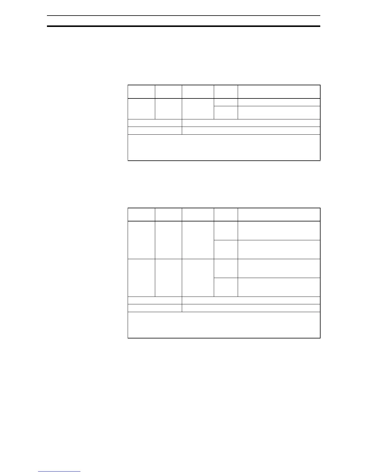
4-6-12 Torque Limited Signal
The inverter outputs the torque limited signal when it is in torque limit opera-
tion.
To enable this function, assign "
10 (TRQ)" to an intelligent output terminal.
Refer to SECTION 3 Configuring Drive Parameters on page 59 for detailed
explanation.
4-6-13 Running Time and Power On Time Over Signal
The inverter outputs the operation time expiration signal and power on time
expiration signal.
To enable this function, assign "
11 (RNT)", and/or "12 (ONT)" to intelligent out-
put terminals.
Option
Code
Terminal
Symbol
Function
Name
State Description
10 TRQ Torque lim-
ited signal
ON Inverter is in torque limiting mode
OFF Inverter is not in torque limiting
mode
Valid for inputs: 11, 12, AL0 - AL2
Required settings: A044=03, b040~b044
Notes:
• The example circuit for terminal [11] drives a relay coil. Note the use of a diode to
prevent the negative-going turn-off spike generated by the coil from damaging the
inverter's output transistor.
Option
Code
Terminal
Symbol
Function
Name
State Description
11 RNT Run time
expiration
signal
ON Accumulated operation time of
the inverter exceeds the set value
of b034
OFF Accumulated operation time of
the inverter does not exceed the
set value of b034
12 ONT Power ON
time expira-
tion signal
ON Accumulated power on time of
the inverter exceeds the set value
of b034
OFF Accumulated power on time of
the inverter does not exceed the
set value of b034
Valid for inputs: 11, 12, AL0 - AL2
Required settings: B034
Notes:
• The example circuit for terminal [11] drives a relay coil. Note the use of a diode to
prevent the negative-going turn-off spike generated by the coil from damaging the
inverter's output transistor.