EasyManuals Logo

Omron MX2 User Manual

Omron MX2
356 pages
To Next Page IconTo Next Page
To Previous Page IconTo Previous Page
Page #66 background imageLoading...
Page #66 background image
44
Step-by-Step Basic Installation Section 2-3
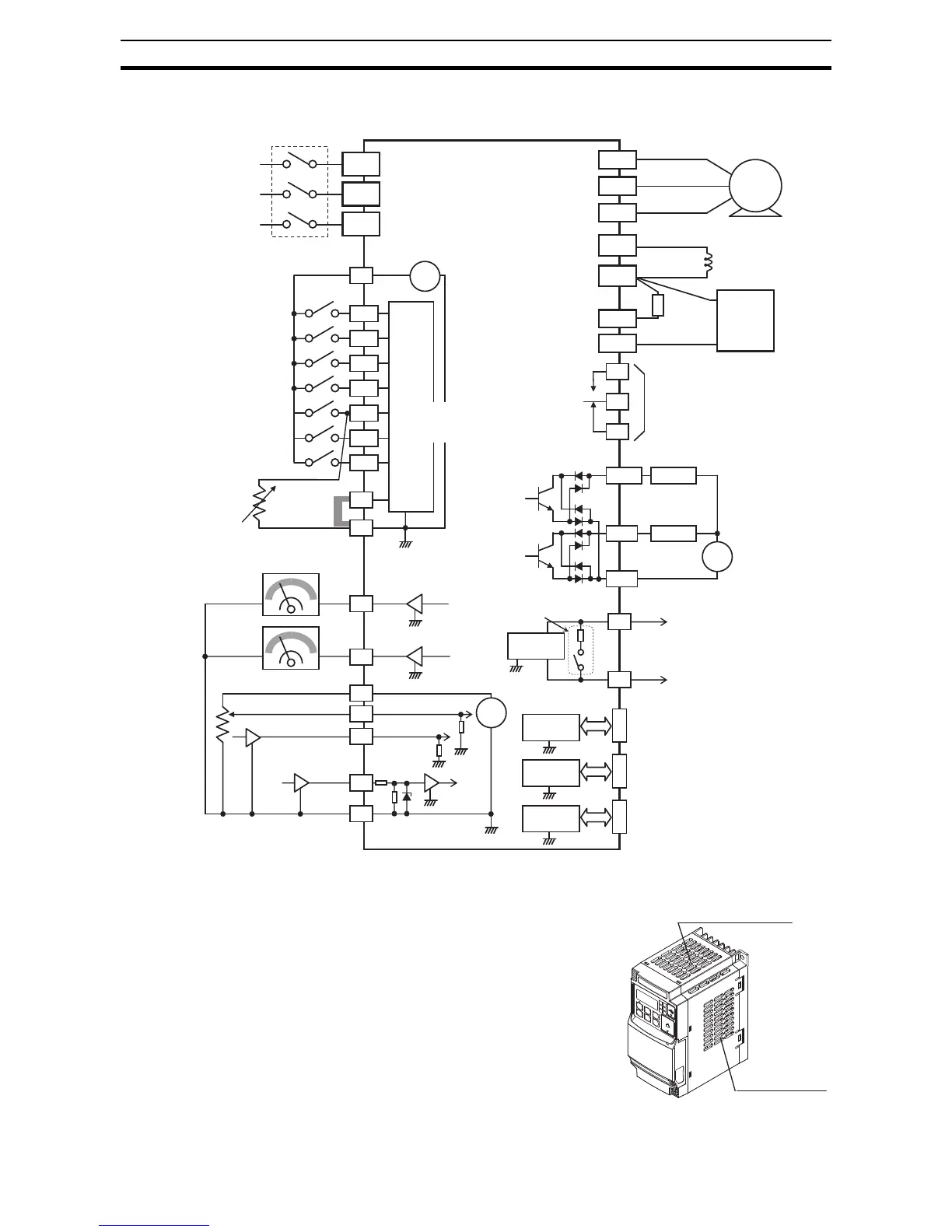
MX2 control wiring quick reference
2-3-15 Uncover the Inverter Vents
Step 5 After mounting and wiring the inverter,
remove any covers from the inverter hous-
ing. This includes material over the side ven-
tilation ports.
!WARNING Make sure the input power to the inverter is
OFF. If the drive has been powered, leave it
OFF for ten minutes before continuing.
Breaker, MCCB
or GFI
Power source,
3-phase or
1-phase, per
inverter model
Input
circuits
24V
P24
+ -
1
2
3/GS1
4/GS2
5/PTC
Forward
Thermistor
Intelligent inputs,
7 terminals
GND for logic inputs
NOTE:
For the wiring of intelligent
I/O and analog inputs,
be sure to use twisted
pair / shielded cable.
Attach the shielded wire
for each signal to its
respective common
terminal at the inverter
end only.
Input impedance of
each intelligent input is
4.7 kΩ
[5] configurable as
discrete input or
thermistor input
AM
Volt. Meter
H
L
0~10VDC
4~20mA
GND for analog signals
MX2
Motor
PD/+1
P/+
R
(
L1
)
S
(
L2
)
T
N
(
L3
)
U
(T1)
V
(T2)
W
(T3)
Braking
unit
(optional)
N/-
DC reactor
(optional)
AL1
AL0
AL2
Relay contacts,
type 1 Form C
6
7/EB
EO
Freq. Meter
RB
Brake
resistor
(optional)
11/EDM
Load
Freq. arrival signal
Open collector output
Output circuit
Common for logic outputs
12
Load
+
-
CM2
L
L
+
-
O
OI
EA
10 VDC
RJ45 port
(Optional operator port)
transceiver
USB (mini-B) port
(PC communication port)
USB power: Self power
L
L
Option port
controller
Option port connector
L
L
L
L
L
L
SP
SN
L
PLC
Short bar
(Source type)
Analog reference
Pulse train input
24 VDC 32 kHz max.
Apprx.100 Ω
Apprx.10 Ω
Termination resistor (200 Ω)
(Change by slide switch)
RS485
transceiver
Serial communication port
(RS485/ModBus)
RS485
transceiver
USB
transceiver
Ventilation holes (top)
Ventilation holes
(both sides)

Table of Contents

Other manuals for Omron MX2

Questions and Answers:

Question and Answer IconNeed help?

Do you have a question about the Omron MX2 and is the answer not in the manual?

Omron MX2 Specifications

General IconGeneral
ModelMX2
CategoryInverter
Enclosure RatingIP20
Control MethodV/f control, Sensorless vector control
Frequency Range0.1 to 400 Hz
ProtectionOvercurrent, Overvoltage, Undervoltage, Overheat, Short circuit
CommunicationModbus RTU
Ambient Temperature-10 to 50 °C (without freezing or condensation)
Overload Capacity150% for 60 seconds
Cooling MethodFan Cooled
Humidity5 to 95% RH (without condensation)
AltitudeUp to 1000m without derating
Voltage200-240 VAC, 380-480 VAC
Braking UnitBuilt-in (for certain models), Optional External

Related product manuals