72
"A" Group: Standard Functions Section 3-5
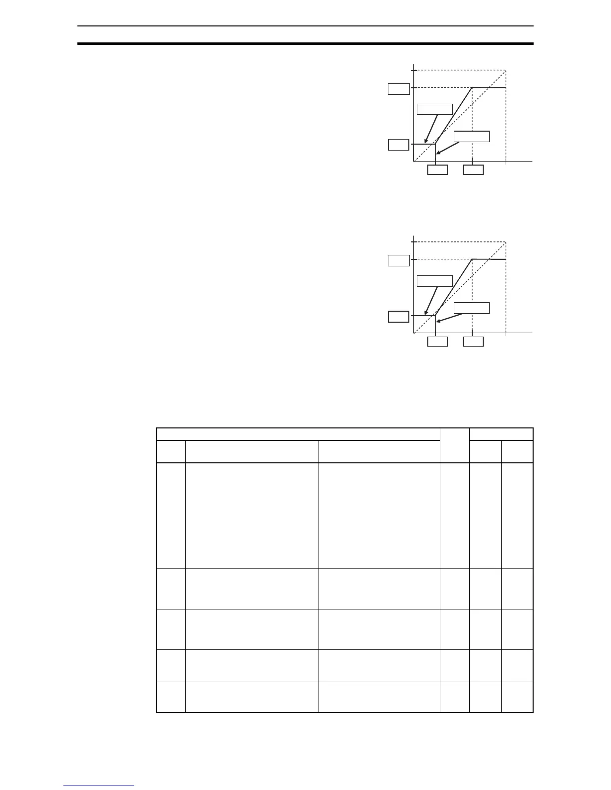
Adjusting [O-L] characteristics - In
the graph to the right,
A013 and A014
select the active portion of the input
voltage range. Parameters
A011 and
A012 select the start and end frequency
of the converted output frequency
range, respectively. Together, these four
parameters define the major line seg-
ment as shown. When the line does not
begin at the origin (
A011 and A013 > 0),
then
A015 defines whether the inverter
outputs 0 Hz or the
A011-specified fre-
quency when the analog input value is
less than the
A013 setting. When the input voltage is greater than the A014
ending value, the inverter outputs the ending frequency specified by A012.
Adjusting [OI-L] characteristics - In
the graph to the right,
A103 and A104
select the active portion of the input
current range. Parameters
A101 and
A102 select the start and end frequency
of the converted output frequency
range, respectively. Together, these four
parameters define the major line seg-
ment as shown. When the line does not
begin at the origin (
A101 and A103 > 0),
then
A105 defines whether the inverter
outputs 0 Hz or the
A101-specified fre-
quency when the analog input value is
less than the
A103 setting. When the input voltage is greater than the A104
ending value, the inverter outputs the ending frequency specified by A102.
Adjusting [VR-L] characteristics - This is used when an optional operator is
used. Refer to parameters
A161 ~ A165 for the details.
Max frequency
A012
A011
A014
100%
0V
10V
A013
0%
A015=00
A015=01
0
Input scale
%
"A" Function Run
Mode
Edit
Defaults
Func.
Code
Name Description EU Units
A005 [AT] selection Three options; select codes:
00... Select between [O] and
[OI] at [AT] (ON=OI,
OFF=O)
02...Select between [O] and
external POT at [AT]
(ON=POT, OFF=O)
03...Select between [OI] and
external POT at [AT]
(ON=POT, OFF=OI)
8 00 –
A011 [O] input active range start fre-
quency
The output frequency corre-
sponding to the analog input
range starting point, range is
0.00 to 400.0
*1
8 0.00 Hz
A012 [O] input active range end fre-
quency
The output frequency corre-
sponding to the analog input
range ending point, range is
0.0 to 400.0
*2
8 0.00 Hz
A013 [O] input active range start voltage The starting point (offset) for
the active analog input range,
range is 0. to 100.
8 0. %
A014 [O] input active range end voltage The ending point (offset) for
the active analog input range,
range is 0. to 100.
8 100. %