73
"A" Group: Standard Functions Section 3-5
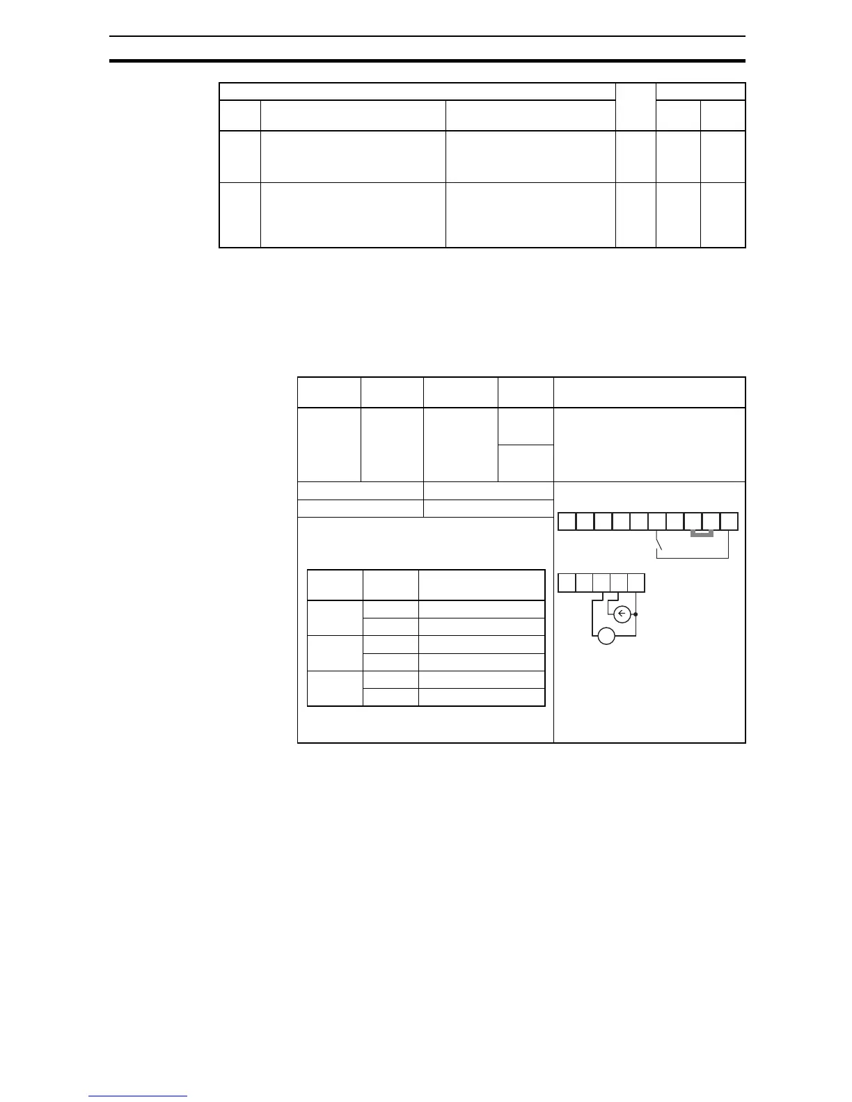
The [AT] terminal selects whether the inverter uses the voltage [O] or current
[OI] input terminals for external frequency control. When intelligent input [AT]
is ON, you can set the output frequency by applying a current input signal at
[OI]-[L]. When the [AT] input is OFF, you can apply a voltage input signal at
[O]-[L] to set the output frequency. Note that you must also set parameter
A001
= 01 to enable the analog terminal set for controlling the inverter frequency.
If [AT] is not assigned to any of the intelligent input terminal, inverter recog-
nizes the input [O]+[OI].
A016: External Frequency Filter Time Constant - This filter smoothes the
analog input signal for the inverter's output frequency reference.
•
A016 sets the filter range from n=1 to 30. This is a simple moving average
calculation, where n (number of samples) is variable.
•
A016=31 is a special value. It configures the inverter to use a movable
deadband feature. Initially the inverter uses the 500 ms of filter time con-
stant. Then, the deadband is employed for each subsequent average of
16 samples. The deadband works by ignoring small fluctuations in each
new average: less than ±0.1 Hz change. When a 30-sample average
exceeds this deadband, then the inverter applies that average to the out-
put frequency reference, and it also becomes the new deadband compar-
ison point for subsequent sample averages.
A015 [O] input start frequency enable Two options; select codes:
00... Use offset (A011 value)
01... Use 0Hz
8 01 –
A016 Analog input filter Range n = 1 to 31,
1 to 30 : ×2ms filter
31: 500ms fixed filter with
±0.1kHz hys.
8 8. Spl.
*1
Up to 1000Hz for High frequency mode (d060 set to "2")
*2
Up to 1000Hz for High frequency mode (d060 set to "2")
"A" Function Run
Mode
Edit
Defaults
Func.
Code
Name Description EU Units
Option
Code
Terminal
Symbol
Function
Name
State Description
16 AT An al og
Input
Voltage/
Current
Select
ON See the table down below
OFF
Valid for inputs: C001~C007 Example :
See I/O specs on page 169.
Required settings: A001 = 01
Notes:
Combination of A005 setting and [AT] input for
analog input activation.
• Be sure to set the frequency source setting
A001=01 to select the analog input terminals.