247
Maintenance and Inspection Section 6-4
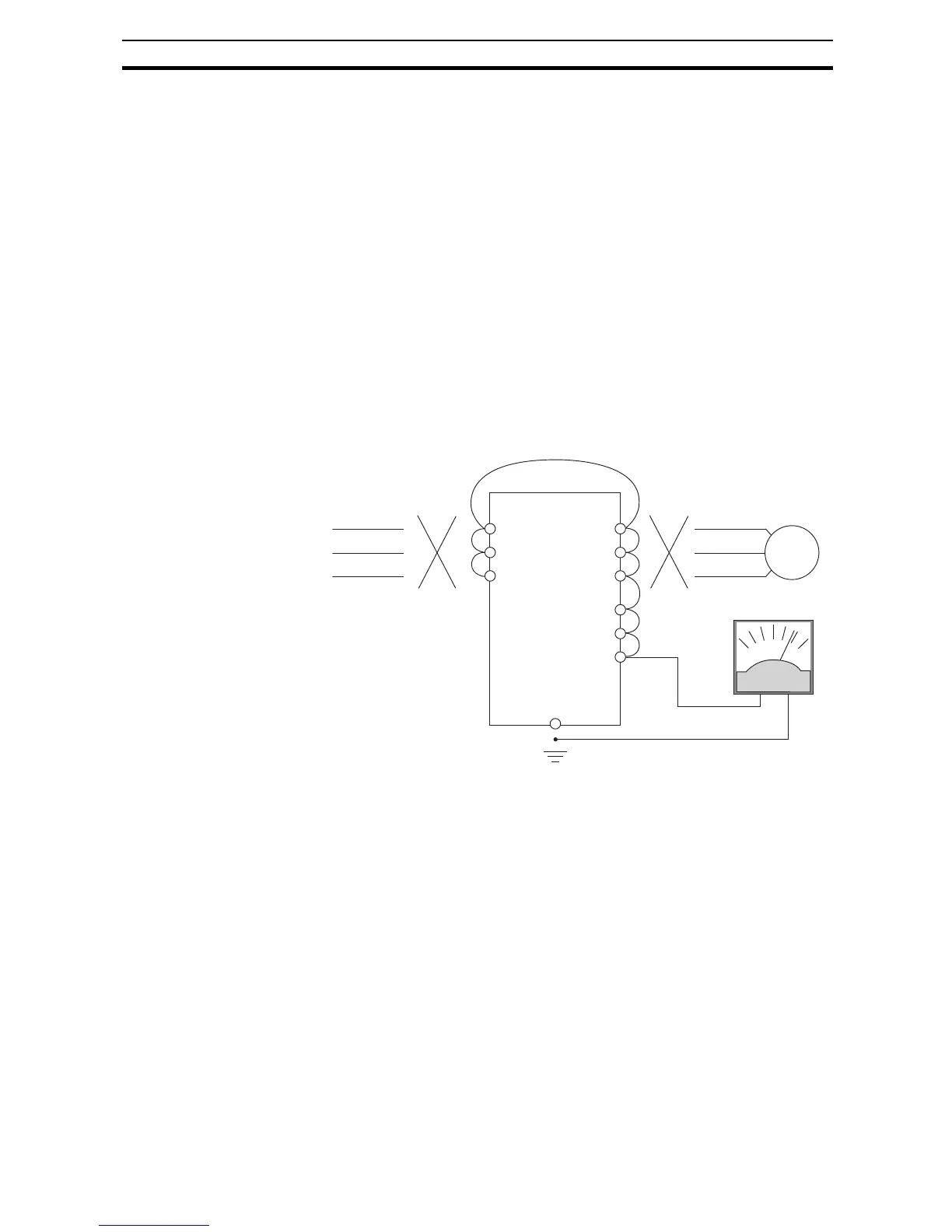
6-4-2 Megger test
The megger is a piece of test equipment that uses a high voltage to determine
if an insulation degradation has occurred. For inverters, it is important that the
power terminals be isolated from the Earth GND terminal via the proper
amount of insulation.
The circuit diagram below shows the inverter wiring for performing the megger
test. Just follow the steps to perform the test:
1. Remove power from the inverter and wait at least 5 minutes before pro-
ceeding.
2. Open the front housing panel to access the power wiring.
3. Remove all wires to terminals [R, S, T, PD/+1, P/+, N/-, U, V, and W]. Most
importantly, the input power and motor wires will be disconnected from the
inverter.
4. Use a bare wire and short terminals [R, S, T, PD/+1, P/+, N/-, U, V, and W]
together as shown in the diagram.
5. Connect the megger to the inverter Earth GND and to the shorted power
terminals as shown. Then perform the megger test at 500 VDC and verify
5MΩ or greater resistance.
6. After completing the test, disconnect the megger from the inverter.
7. Reconnect the original wires to terminals [R, S, T, PD/+1, P/+, N/-, U, V,
and W].
!Caution Do not connect the megger to any control circuit terminals such as intelligent
I/O, analog terminals, etc. Doing so could cause damage to the inverter.
!Caution Never test the withstand voltage (HIPOT) on the inverter. The inverter has a
surge protector between the main circuit terminals above and the chassis
ground.
!Caution Power terminal assignment is different compared to old models such as L100,
L200 series, etc,. Pay attention when wiring the power cable.
Disconnect
power source
MX2
R
S
T
U
V
W
PD/+1
P /+
N/–
Earth GND
Add test jumper wire
Disconnect
motor wires
Megger, 500 VDC
Motor