38
Step-by-Step Basic Installation Section 2-3
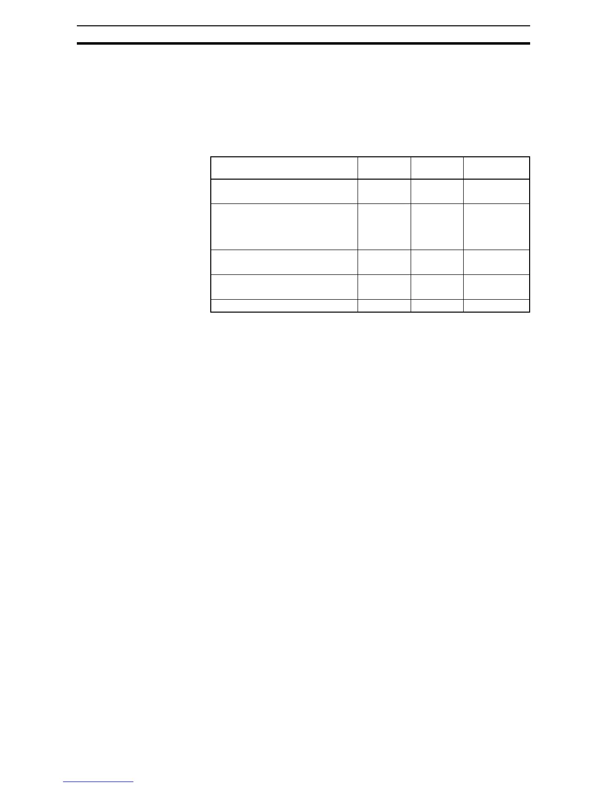
2-3-7 Terminal Dimensions and Torque Specs
The terminal screw dimensions for all MX2 inverters are listed in table below.
This information is useful in sizing spade lug or ring lug connectors for wire
terminations.
!Caution Tighten the screws with the specified torque in the table below. Check for any
loosening of screws. Otherwise, there is the danger of fire.
2-3-8 Inverter Supply Input (R/L1, S/L2, T/L3)
Step 3 In this step, you will connect wiring to the input of the inverter. First, you must
determine whether the inverter model you have required three-phase power
only with terminals [R/L1], [S/L2], and [T/L3], or single-phase power only
with terminals [L1] and [N]. Refer to the specifications label (on the side of the
inverter) for the acceptable power source types!
2-3-8-1 Earth leakage circuit breaker
Use an earth leakage breaker for circuit (wiring) protection between the power
supply and the main power supply terminals (R/L1, S/L2, T/L3).
An earth leakage breaker may malfunction at high frequencies as those gen-
erated by an inverter. Use an earth leakage breaker with a large high-fre-
quency sensitive current rating.
When sensitivity of 30mA or even less earth leakage maybe required in cer-
tain applications (e.g. domestic), short motor cable and convenient low-leak-
age EMC filters should be selected. Check with your supplier for additional
indications.
2-3-8-2 Magnetic contactor
When the Inverter protective function is activated, your system may fail or an
accident may occur. Connect a magnetic contactor to turn off the Inverter
power supply.
Do not start or stop the Inverter by switching ON/OFF the magnetic contactor
provided in the Inverter power supply input (primary) circuit and output (sec-
ondary) circuit.To start or stop the Inverter via an external signal, use the
operation command terminals (FW, RV) on the control circuit terminal block.
Do not use this Inverter with an input phase loss connection. The Inverter
operating with 1-phase input may be causing a trip (due to undervoltage,
overcurrent, etc.) or damage to the Inverter.
Do not turn on the power and then turn it off again more than once every 3
minutes. Doing so may damage the Inverter.
Types Screw
Diameter
Width (mm) Tightening
Torque (N·m)
MX2 - AB001, AB002, AB004
MX2 - A2001, A2002, A2004, A2007
M3.5 7.6 1.0
MX2 - AB007, AB015, AB022
MX2 - A2015, A2022, A2037
MX2 - A4004, A4007, A4015, A4022,
A4030, A4040
M4 10 1.4
MX2 - A2055, A2075
MX2 - A4055, A4075
M5 13 3.0
MX2 - A2110
MX2 - A4110, A4150
M6 17.5 3.9 to 5.1
MX2 - A2150 M8 23 5.9 to 8.8