29
Step-by-Step Basic Installation Section 2-3
used in an environment exceeding the allowable operating temperature range,
the product life of the Inverter (specifically, the capacitor) will be shortened.
Measure and check the temperature approx. 5 cm from the bottom center of
the Inverter body.
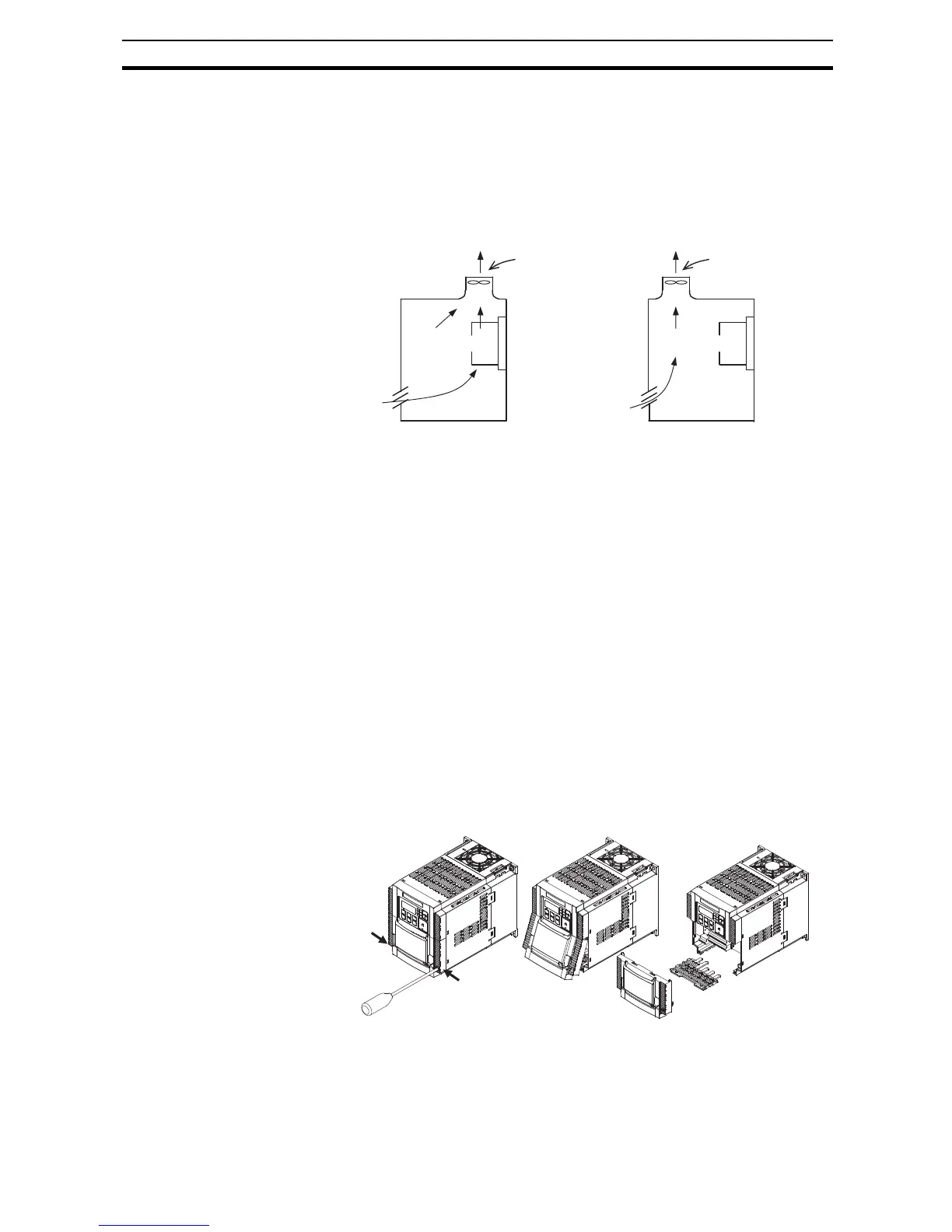
Provide sufficient space around the Inverter because it can become very hot
(up to 150°C or so). Or provide the right air ventilation forced cooling flow
when designing the enclosure :
Keep the Inverter away from heating elements (such as a Braking Resistor,
reactor, etc.).
Although side-by-side installation is possible. The ambient temperature of the
installation site must not exceed 40°C and the carrier frequency and output
current must be derated if side-by-side installation is used. For details check
Derating Curves on page 9.
Make sure that the humidity in the installation site is within the allowable oper-
ating range (20% to 90% RH), as defined in the standard specifications.
!Caution Be sure to maintain the specified clearance area around the inverter and to
provide adequate ventilation. Otherwise, the inverter may overheat and cause
equipment damage or fire.
2-3-3 Installation/Removal Method of the Terminal Block Cover
2-3-3-1 Removal method
The terminal block cover is secured with one screw at the bottom right for 3.0
kW and smaller models, or with two screws on both sides for 3.7 kW and
larger models.
Ventilation fan
Ventilation fan
Inverter
Inverter
(Good example) (Bad example)
While pressing here in the direction
of the arrow, pull the terminal block
cover downward to remove.
Loosen the screw(s) (1 or 2
locations) securing the
terminal block cover.
While pressing the bottom of the
terminal block cover in the direction
of the arrow, pull the terminal block
cover downward to remove.