220
Using Intelligent Output Terminals Section 4-6
4-6-28 Inverter Ready Signal
The inverter outputs the inverter ready signal (IRDY) when it is ready for oper-
ation (i.e. when it can receive an operational command).
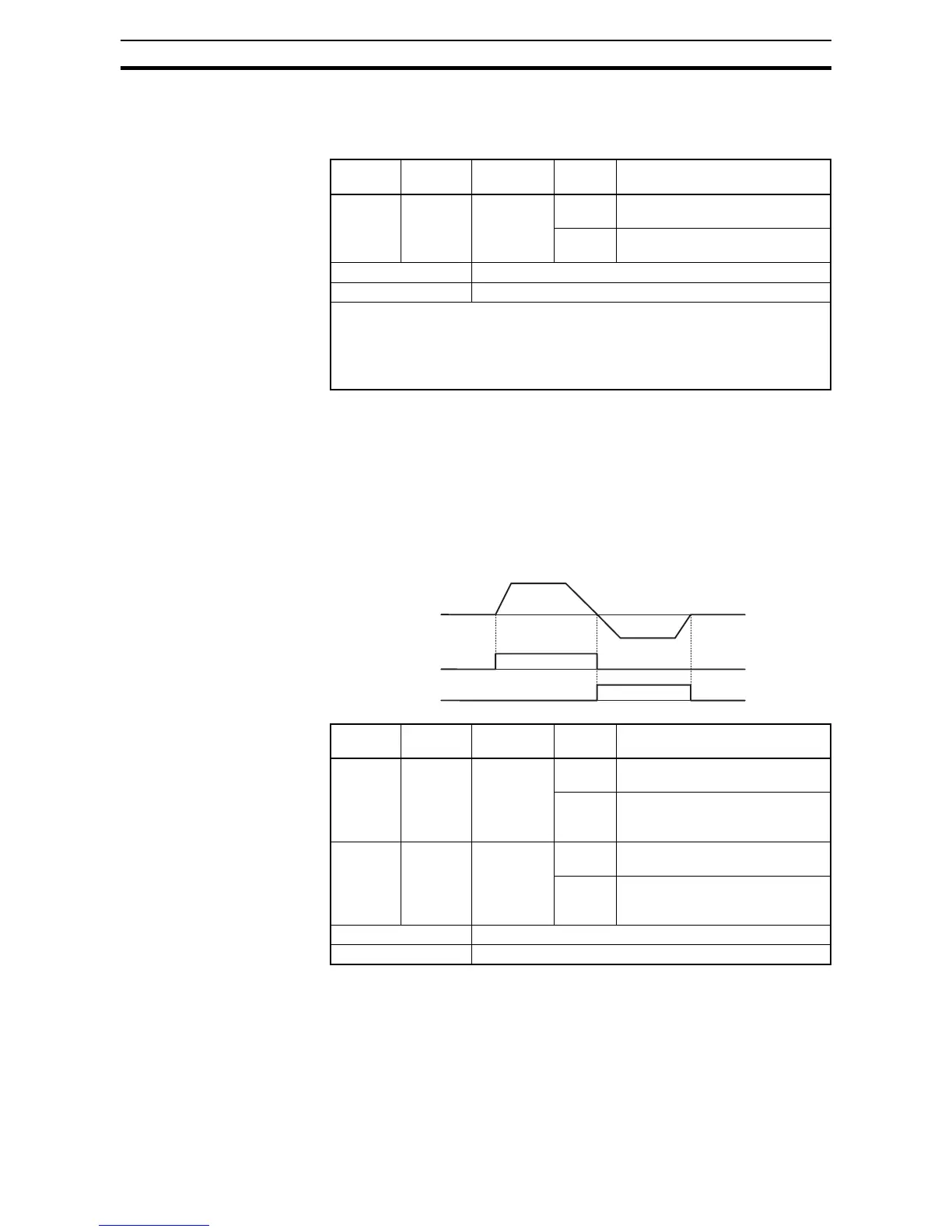
4-6-29 Forward Rotation, Reverse Rotation Signals
Forward Rotation signal – The inverter continues to output the forward rota-
tion signal (FWR) while it is driving the motor for forward operation. The FWR
signal is turned off while the inverter is driving the motor for reverse operation
or stopping the motor.
Reverse Rotation signal – The inverter continues to output the forward rota-
tion signal (RVR) while it is driving the motor for reverse operation. The RVR
signal is turned off while the inverter is driving the motor for forward operation
or stopping the motor.
Option
Code
Terminal
Symbol
Function
Name
State Description
50 IRDY Inverter
ready signal
ON The inverter is ready to accept the
operation command
OFF The inverter is not ready to accept
the operation command
Valid for inputs: 11, 12, AL0 - AL2
Required settings: C038, C039
Notes:
• The inverter can recognize only the operation command is given while the IRDY
signal is given out
• If the IRDY signal is not given out, check whether the input power supply voltage
(connect to the R, S, and T terminals) is within the range of specification
Option
Code
Terminal
Symbol
Function
Name
State Description
51 FWR Forward
rotation
ON Inverter is driving the motor for
forward operation
OFF Inverter is driving the motor for
reverse operation, or the motor is
stopped
52 RVR Reverse
rotation
ON Inverter is driving the motor for
reverse operation
OFF Inverter is driving the motor for
forward operation, or the motor is
stopped
Valid for inputs: 11, 12, AL0 - AL2
Required settings:
Output freq.
Forward rotation signal (FWR)
Reverse rotation signal (RVR)