170
Control Logic Signal Specifications Section 4-3
Note 1 The two terminals [L] are electrically connected together inside the inverter.
Note 2 We recommend using [L] logic GND (to the right) for logic input circuits and [L]
analog GND (to the left) for analog I/O circuits.
Note 3 Default relay N.O./N.C. configuration is reversed. See 4-5-11 Force Operation
from Digital Operator on page 188.
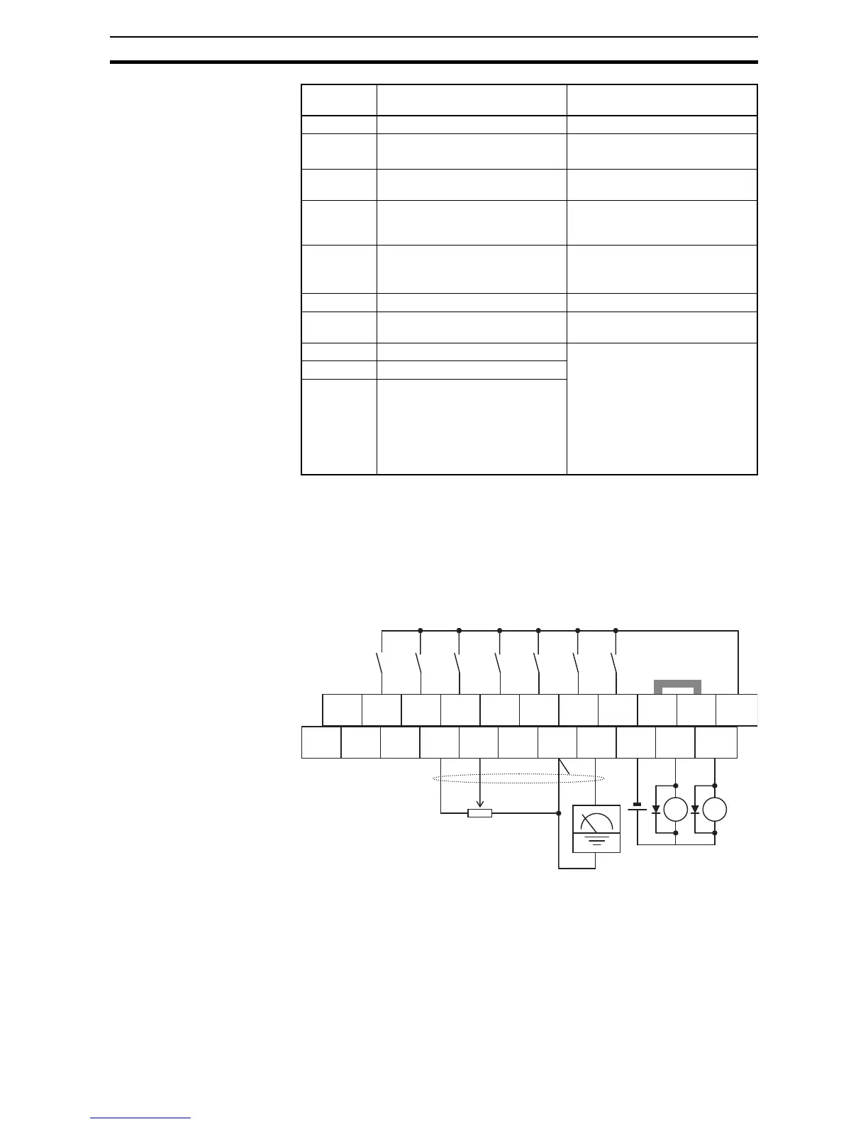
4-3-1 Wiring sample of control logic terminal (source logic)
Note If relay is connected to intelligent output, install a diode across the relay coil
(reverse-biased) in order to suppress the turn-off spike.
AM Analog voltage output 0~10 VDC 1 mA maximum
EO Pulse train output 10 VDC 2 mA maximum
32 kHz maximum
L (bottom
row) *2
GND for analog signals Sum of [OI], [O], and [H] currents
(return)
OI Analog current input 4 to 19.6 mA range,
20 mA nominal,
input impedance 250 Ω
O Analog voltage input 0 to 9.8 VDC range,
10 VDC nominal,
input impedance 10 Ω
H +10 V analog reference 10 VDC nominal, 10 mA max.
SP, SN Serial communication terminal For RS485 Modbus communica-
tion.
AL0 Relay common contact 250 VAC 2.5 A (R load) max.
250 VAC 0.2 A (I load, P.F.=0.4)
max.
100 VAC 10 mA min.
30 VDC 3.0 A (R load) max.
30 VDC 0.7 A (I load, P.F.=0.4)
max.
5VDC 100mA min.
AL1 *3 Relay contact, normally open
AL2 *3 Relay contact, normally closed
Terminal
Name
Description Ratings