216
Using Intelligent Output Terminals Section 4-6
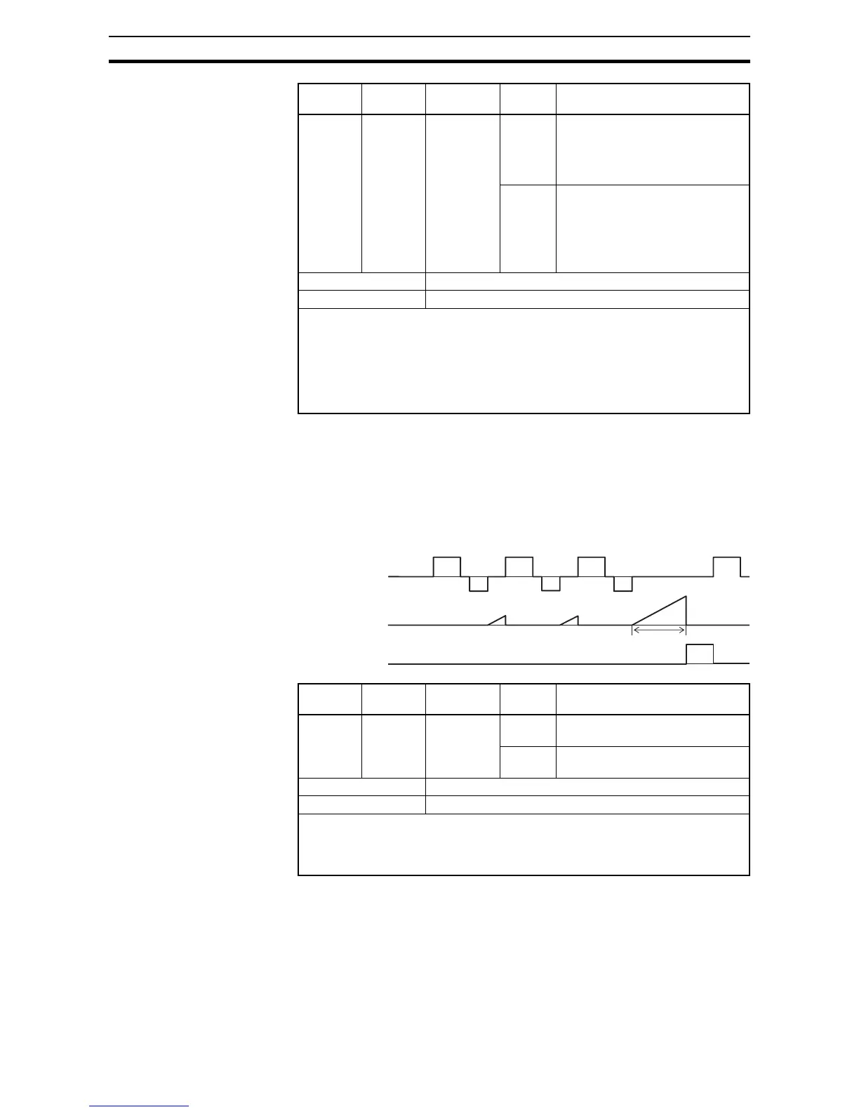
4-6-21 Communication signal Disconnect Detect
This signal function is enabled only when ModBus-RTU has been selected for
the communication. If a reception timeout occurs, the inverter continues to
output the communication line disconnection signal until it receives the next
data.
Specify the limit time for reception timeout by setting the communication trip
time (
C077).
Option
Code
Terminal
Symbol
Function
Name
State Description
31 FBV Feedback
Value Check
ON • Transitions to ON when the
inverter is in RUN Mode and the
PID Process Variable (PV) is less
than the Feedback Low Limit
(C053)
OFF • Transitions to OFF when the PID
Feedback Value (PV) exceeds
the PID High Limit (C052)
• Transitions to OFF when the
inverter goes from Run Mode to
Stop Mode
Valid for inputs: 11, 12, AL0 - AL2
Required settings: A076, C052, C053
Notes:
• The [FBV] is designed for implementing two-stage control. The PV high limit and
PV low limit parameters, C052 and C053, do not function as process alarm thresh-
olds. Terminal [FBV] does not provide a PID alarm function.
• The example circuit for terminal [11] drives a relay coil. Note the use of a diode to
prevent the negative-going turn-off spike generated by the coil from damaging the
inverter's output transistor.
Option
Code
Terminal
Symbol
Function
Name
State Description
32 NDc Communi-
cation signal
disconnect
detection
ON When there is a disconnection in
communiciation
OFF When there is no disconnection in
communiciation
Valid for inputs: 11, 12, AL0 - AL2
Required settings: C077
Notes:
• The example circuit for terminal [11] drives a relay coil. Note the use of a diode to
prevent the negative-going turn-off spike generated by the coil from damaging the
inverter's output transistor.