15
Introduction to Variable-Frequency Drives Section 1-3
Today, with the advent of sophisticated microprocessors and digital signal pro-
cessors (DSPs), it is possible to control the speed and torque of AC induction
motors with unprecedented accuracy. The MX2 utilizes these devices to per-
form complex mathematical calculations required to achieve superior perfor-
mance. You can choose various torque curves to fit the needs of your
application. Constant torque applies the same torque level across the fre-
quency (speed) range. Variable torque, also called reduced torque, lowers the
torque delivered at mid-level frequencies. A torque boost setting will add addi-
tional torque in the lower half of the frequency range for the constant and vari-
able torque curves. With the free-setting torque curve feature, you can specify
a series of data points that will define a custom torque curve to fit your appli-
cation.
1-3-4 Inverter Input and Three-phase Power
The Omron MX2 Series of inverters includes two sub-groups: the 200 V class
and the 400V class inverters. The drive described in this manual may be used
in either the United States or Europe, although the exact voltage level for com-
mercial power may be slightly different from country to country. Accordingly, a
200 V class inverter requires (nominal) 200 to 240 VAC, and 400 V class
inverter requires from 380 to 480 VAC.
The 200 V class inverters MX2-B accept single-phase 200 V class input volt-
age, those MX2-2 three-phase power only. All 400 V class inverters require
three-phase power supply.
!Tip If your application only has single phase power available, refer to MX2 inverter
of 3HP or less; they can accept single phase input power. Note: Larger mod-
els may be able to accept single-phase with derating. Contact your Omron
distributor for assistance.
The common terminology for single phase power is line (L) and Neutral (N).
Three-phase power connections are usually labeled Line 1 [R/L1], Line 2 [S/
L2] and Line 3 [T/L3]. In any case, the power source should include an earth
ground connection. That ground connection will need to connect to the
inverter chassis and to the motor frame (see "Wire the Inverter Output to
Motor" in section 2-3-12 (page 43) and "Inverter output terminal (U/T1, V/T2,
W/T3)" in section 2-3-9 (page 39)).
1-3-5 Inverter Output to the Motor
The AC motor must be connected only to the inverter's
output terminals. The output terminals are uniquely
labeled (to differentiate them from the input terminals)
with the designations U/T1, V/T2, and W/T3. This cor-
responds to typical motor lead connection designations
T1, T2, and T3. It is often not necessary to connect a
particular motor lead for a new application. The conse-
quence of swapping any two of the three connections is
the reversal of the motor direction. In applications
where reversed rotation could cause equipment dam-
age or personnel injury, be sure to verify direction of
rotation before attempting full-speed operation.
For safety to personnel, you must connect the motor chassis ground to the
ground connection at the bottom of the inverter housing.
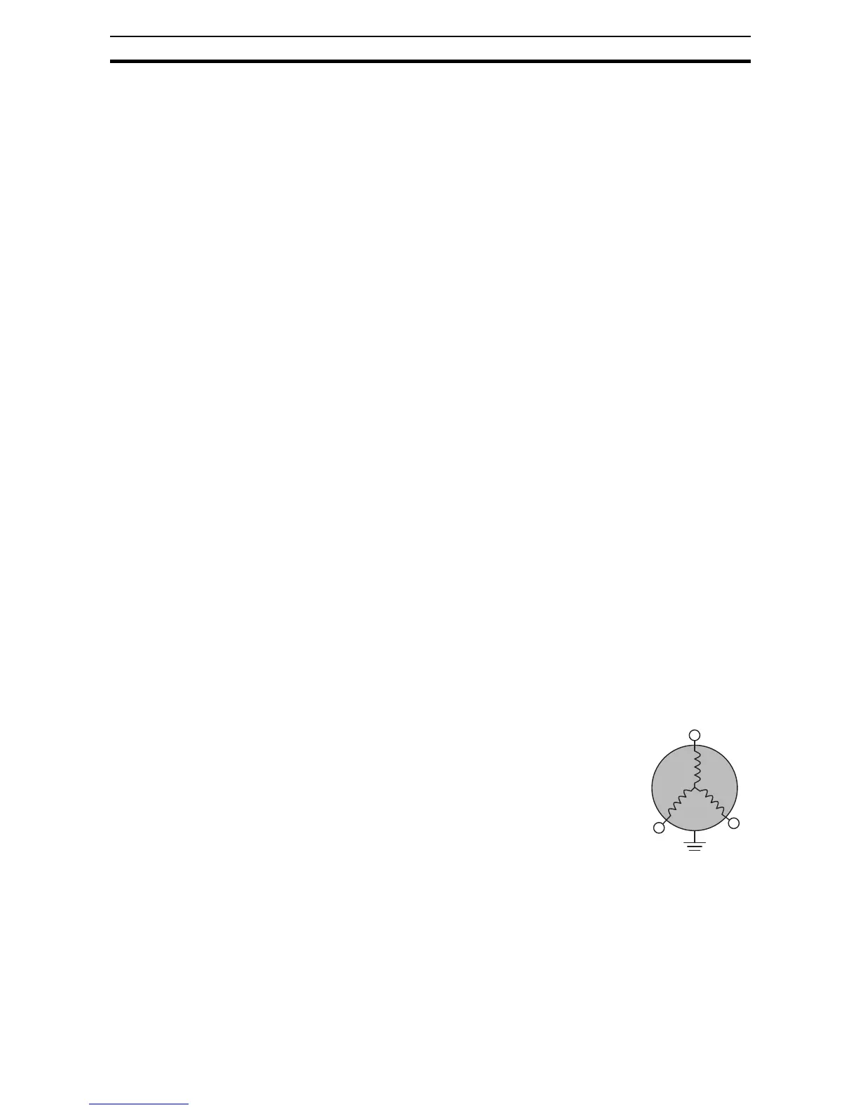
Notice the three connections to the motor do not include one marked "Neutral"
or "Return". The motor represents a balanced "Y" impedance to the inverter,
so there is no need for a separate return. In other words, each of the three
"Hot" connections serves also as a return for the other connections, because
of their phase relationship.
3-phase AC motor
U/T1
V/T2
W/T3
Earth GND