169
Control Logic Signal Specifications Section 4-3
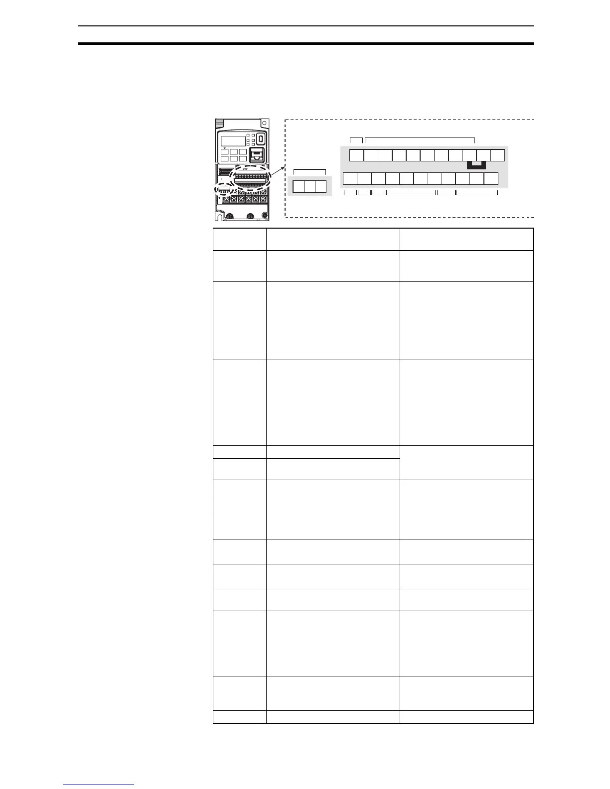
4-3 Control Logic Signal Specifications
The control logic connectors are located just behind the front housing cover.
The relay contacts are just to the left of the logic connectors. Connector label-
ing is shown below.
Terminal
Name
Description Ratings
P24 +24 V for logic inputs 24 VDC, 100 mA including DI
(5mA each).
(do not short to terminal L)
PLC Intelligent input common Factory set: Source type (connect-
ing [P24] to [1]~[7] turns each
input ON). To change to sink type,
remove the short bar between
[PLC] and [L], and connect it
between [P24] and [L]. In this
case, connecting [L] to [1]~[7]
makes each input ON.
1
2
3/GS1
4/GS2
5/PTC
6
7/EB
Discrete logic inputs
(Terminal [3],[4],[5] and [7] have
dual function. See following
description and related pages for
the details.)
Voltage between each input and
PLC
ON voltage: 18 V min.
OFF voltage: 3 V max.
Allowable max. voltage: 27 VDC
Load current: 5 mA (at 24 V)
GS1(3) Safe stop input GS1 Functionality is based on
ISO13849-1
See appendix for the details.
GS2(4) Safe stop input GS2
PTC(5) Motor thermistor input Connect motor thermistor
between PTC and L terminal and
assign [19:PTC] to detect the
motor temperature by tripping
when exceeding 3 kOhm. Set 19
in C005.
EB(7) Pulse train input B 2 kHz max.
Common is [PLC]
EA Pulse train input A 32 kHz max.
Common is [L]
L (upper
row) *1
GND for logic inputs Sum of input [1]~[7] currents
(return)
11/EDM Discrete logic outputs [11]
(Terminal [11] has dual function.
See following description and
related pages for the details.)
5 0mA max. ON state current,
27 VDC max. OFF state voltage
Common is CM2
In case the EDM is selected, the
functionality is based on
ISO13849-1
12 Discrete logic outputs [12] 50 mA max. ON state current,
27 VDC max. OFF state voltage
Common is CM2
CM2 GND for logic output 100 mA: [11], [12] current return