212
Using Intelligent Output Terminals Section 4-6
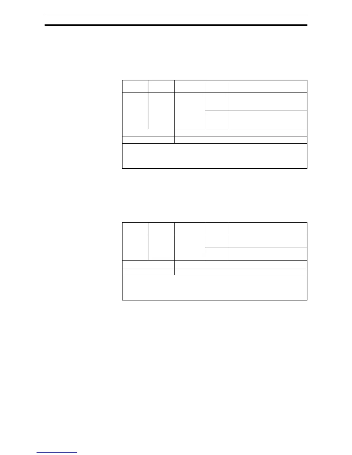
4-6-17 Speed Deviation Excessive Signal
The inverter outputs the detection signal when the deviation between the set
speed and actual motor speed becomes less the threshold level (
P027). This
function is valid when connecting the encoder feedback to the inverter.
To use this function, assign "
22 (DSE)" to one of the intelligent output termi-
nals.
4-6-18 Positioning Completion Signal
Inverter gives out the positioning signal when positioning performance is
done.
To use this function, assign "
23 (POK)" to one of the intelligent output termi-
nals.
Refer to chapter 4 for the details of the performance.
Option
Code
Terminal
Symbol
Function
Name
State Description
22 DSE Speed
deviation
excessive
signal
ON Deviation between the speed
command and motor speed is less
than P027
OFF Deviation between the speed
command and motor speed
exceeds P027
Valid for inputs: 11, 12, AL0 - AL2
Required settings: P027
Notes:
• The example circuit for terminal [11] drives a relay coil. Note the use of a diode to
prevent the negative-going turn-off spike generated by the coil from damaging the
inverter's output transistor.
Option
Code
Terminal
Symbol
Function
Name
State Description
23 POK Positioning
completion
signal
ON Positioning performance is com-
pleted
OFF Positioning performance is not
completed
Valid for inputs: 11, 12, AL0 - AL2
Required settings: P0103~P015
Notes:
• The example circuit for terminal [11] drives a relay coil. Note the use of a diode to
prevent the negative-going turn-off spike generated by the coil from damaging the
inverter's output transistor.