51
Using the Front Panel Keypad Section 2-5
2-5-3 Selecting Functions and Editing Parameters
To prepare to run the motor in the powerup test, this section will show how to
configure the necessary parameters:
1. Select the digital operator as the source of motor speed command
(A001=02).
2. Select the digital operator as the source of the RUN command (A002=02).
3. Set the motor base frequency (A003) and AVR voltage of the motor (A082).
4. Set the motor current for proper thermal protection (b012).
5. Set the number of poles for the motor (H004).
The following series of programming tables are designed for successive use.
Each table uses the previous table's final state as the starting point. There-
fore, start with the first and continue programming until the last one. If you get
lost or concerned that some of the other parameters setting may be incorrect,
refer to "Restoring Factory Default Settings" on page 245.
Prepare to Edit Parameters – This sequence begins with powering ON the
inverter, then it shows how to navigate to the "A" Group parameters for subse-
quent settings. You can also refer to the "Keypad Navigation Map" on page 49
for orientation throughout the steps.
1. Select the digital operator for Speed Command – The inverter output
frequency can be set from several sources, including an analog input, mem-
ory setting, or the network, for example. The powerup test uses the keypad as
the speed control source for your convenience. Note that the default setting
depends on the country.
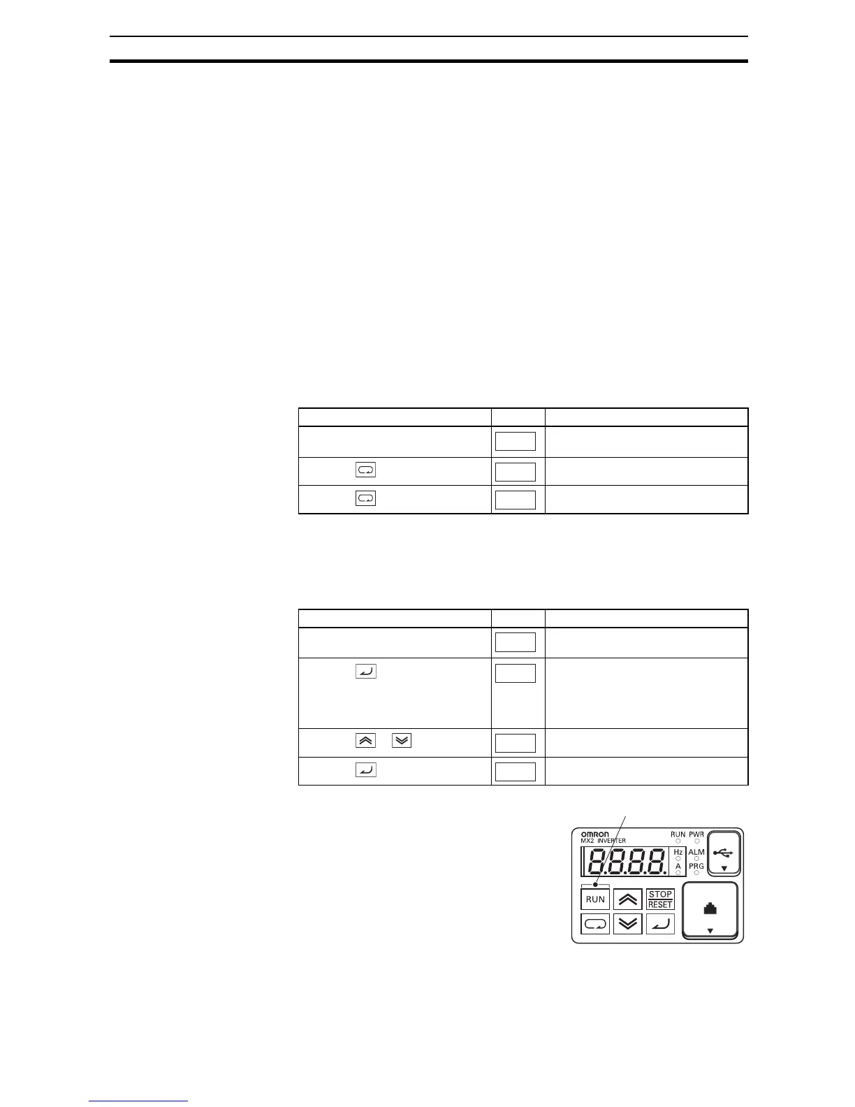
2. Select the digital operator for RUN
Command – To RUN command causes the
inverter to accelerate the motor to the
selected speed. The Run command can
arrive from various sources, including the
control terminals, the Run key on the keypad
or the network. In the figure to the right,
notice the Run Key Enable LED, just above
the Run key. If the LED is ON, the Run key is
already selected as the source, and you may
skip this step. Note that the default setting
depends on the country.
Action Display Func./Parameter
Turn ON the inverter Inverter output frequency displayed
(0Hz in stop mode)
Press the key
"d" group selected
Press the key 2 times
"A" group selected
Action Display Func./Parameter
(Starting point) "A" Group selected
Speed command source setting
Press the key
00... Potentiometer of ext. operator
01... Control terminals
02... Digital operator (F001)
03... ModBus network
etc.
Press the / key to select
02... Digital operator (selected)
Press the key to store
Stores parameter, returns to "A001"
0.0