9
MX2 Inverter Specifications Section 1-2
1-2-3 Signal Ratings
Detailed ratings are in .
1-2-4 Derating Curves
The maximum available inverter current output is limited by the carrier fre-
quency and ambient temperature. Choosing a higher carrier frequency tends
to decrease audible noise, but it also increases the internal heating of the
inverter, thus decreasing (derating) the maximum current output capability.
Ambient temperature is the temperature just outside the inverter housing such
as inside the control cabinet where the inverter is mounted. A higher ambient
temperature decreases (derates) the inverter's maximum current output
capacity.
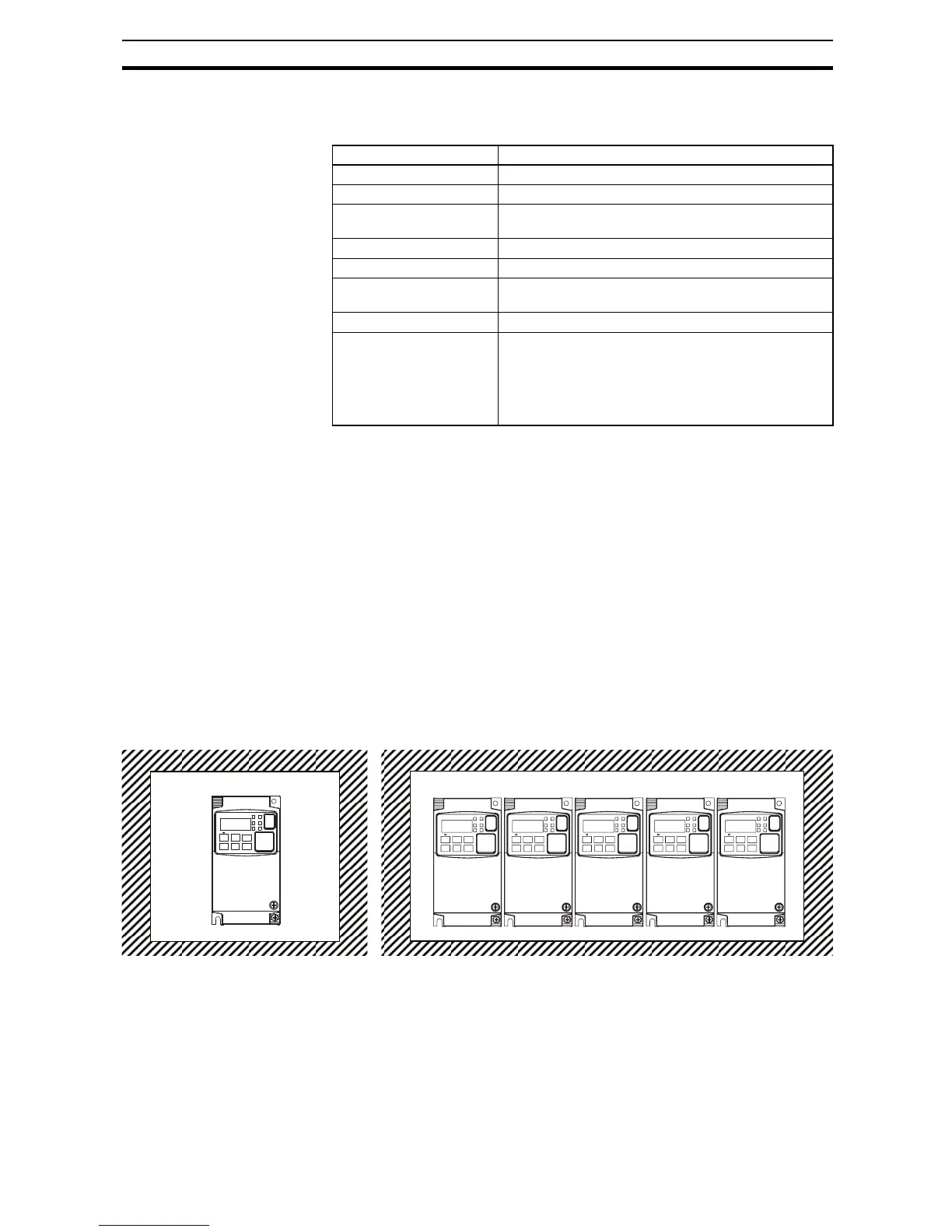
An inverter up to 4.0 kW may be mounted individually in an enclosure or side-
by-side with other inverter(s) as shown below. Side-by-side mounting causes
greater derating than mounting inverters separately. Graphs for either mount-
ing methods are included in this section. Refer to Installation Environment
clearance on page 28 for minimum clearance dimensions for both mounting
configurations.
Signal / Contact Ratings
Built-in power for inputs 24V DC, 30 mA maximum
Discrete logic inputs 27 VDC maximum
Discrete logic outputs 50 mA maximum ON state current, 27 VDC maximum
OFF state voltage
Analog output 10bit / 0 to 10 VDC, 1 mA
Analog input, current 4 to 19.6 mA range, 20 mA nominal
Analog input, voltage 0 to 9.8 VDC range, 10 VDC nominal,
input impedance 10 k
+10 V analog reference 10 VDC nominal, 10 mA maximum
Alarm relay contacts 250 VAC, 2.5 A (R load) max.,
0.2 A (I load, P.F. = 0.4) max.
100 VAC, 10 mA min
30 VDC, 3.0 A (R load) max.,
0.7 A (I load, P.F. = 0.4) max.)
5 VDC, 100 mA min.