71
"A" Group: Standard Functions Section 3-5
3-5-1 Basic Parameter Settings
These settings affect the most fundamental behavior of the inverter - the out-
puts to the motor. The frequency of the inverter's AC output determines the
motor speed. You may select from three different sources for the reference
speed. During application development you may prefer using the potentiome-
ter, but you may switch to an external source (control terminal setting) in the
finished application, for example.
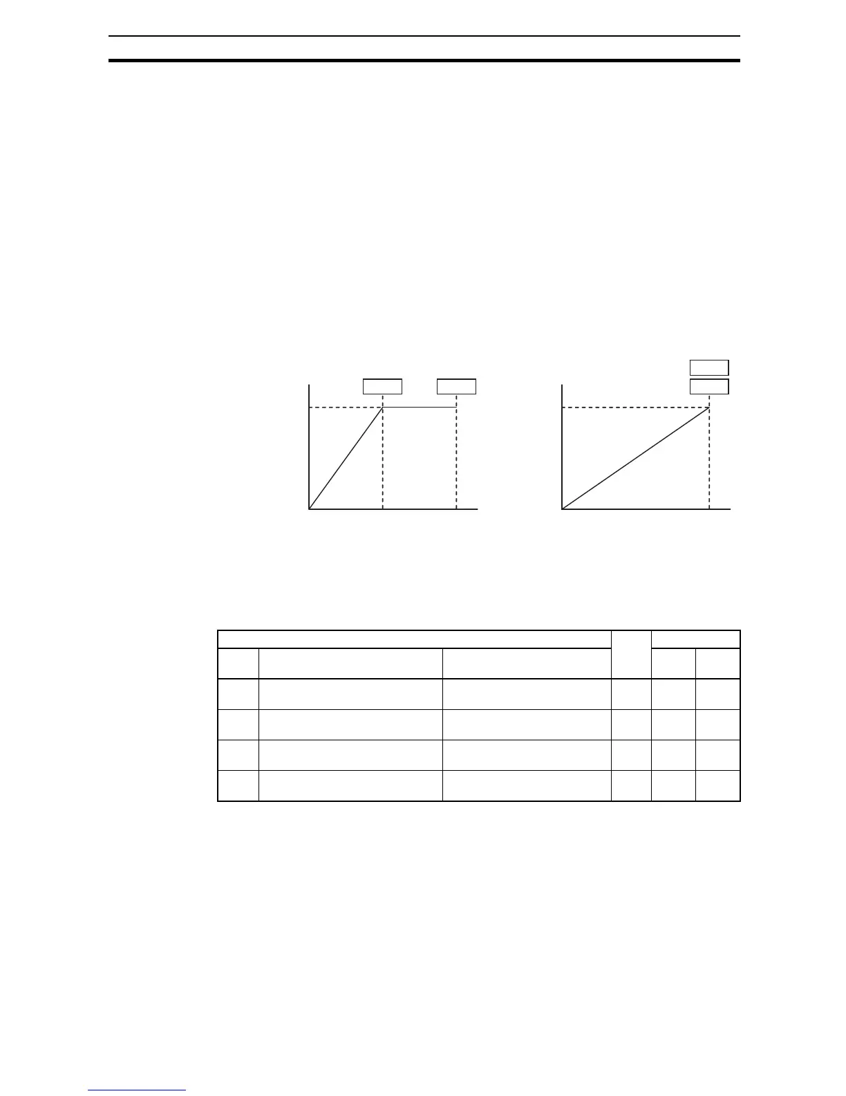
The base frequency and maximum frequency settings interact according to
the graph below (left). The inverter output operation follows the constant V/f
curve until it reaches the full-scale output voltage at the base frequency. This
initial straight line is the constant-torque part of the operating characteristic.
The horizontal line over to the maximum frequency serves to let the motor run
faster, but at a reduced torque. This is the constant-power operating range. If
you want the motor to output constant torque over its entire operating range
(limited to the motor nameplate voltage and frequency rating), then set the
base frequency and maximum frequency equal as shown (below right).
Note The "2nd motor" settings in the table in this chapter store an alternate set of
parameters for a second motor. The inverter can use the 1st set or 2nd set of
parameters to generate the output frequency to the motor. See "Configuring
the Inverter for Multiple Motors" on page 148.
3-5-2 Analog Input Settings
The inverter has the capability to accept an external analog input that can
command the output frequency to the motor. Voltage input (0-10 V) and cur-
rent input (4-20 mA) are available on separate terminals ([O] and [OI] respec-
tively). Terminal [L] serves as signal ground for the two analog inputs. The
analog input settings adjust the curve characteristics between the analog
input and the frequency output.
"A" Function Run
Mode
Edit
Defaults
Func.
Code
Name Description EU Units
A003 Base frequency Settable from 30 Hz to the
maximum frequency (A004)
8 50.0 Hz
A203 Base frequency, 2
nd
motor Settable from 30 Hz to the 2
nd
maximum frequency (A204)
8 50.0 Hz
A004 Maximum frequency Settable from the base fre-
quency to 400 Hz
*1
*1
Up to 1000Hz for High frequency mode (d060 set to "2")
8 50.0 Hz
A204 Maximum frequency, 2
nd
motor Settable from the 2
nd
base fre-
quency to 400 Hz
*2
*2
Up to 1000Hz for High frequency mode (d060 set to "2")
8 50.0 Hz