214
Using Intelligent Output Terminals Section 4-6
4-6-20 PID Second Stage Output
The inverter has a built-in PID loop feature for two-stage control, useful for
certain applications such as building ventilation or heating and cooling
(HVAC). In an ideal control environment, a single PID loop controller (stage)
would be adequate. However, in certain conditions, the maximum output
energy from the first stage is not enough to maintain the Process Variable
(PV) at or near the Setpoint (SP). And, the output of the first stage is in satura-
tion. A simple solution is to add a second stage, which puts an additional and
constant amount of energy into the system under control. When size properly,
the boost from the second stage brings the PV toward the desired range,
allowing the first stage PID control to return to its linear range of operation.
The two-stage method of control has some advantages for particular applica-
tions.
• The second stage is only ON in adverse conditions, so there is an energy
savings during normal conditions.
• Since the second stage is simple ON/OFF control, it is less expensive to
add than just duplicating the first stage.
• At powerup, the boost provided by the second stage helps the process
variable reach the desired setpoint sooner than it would if the first stage
acted alone.
• Even though the second stage is simple ON/OFF control, when it is an
inverter you can still adjust the output frequency to vary the boost it pro-
vides.
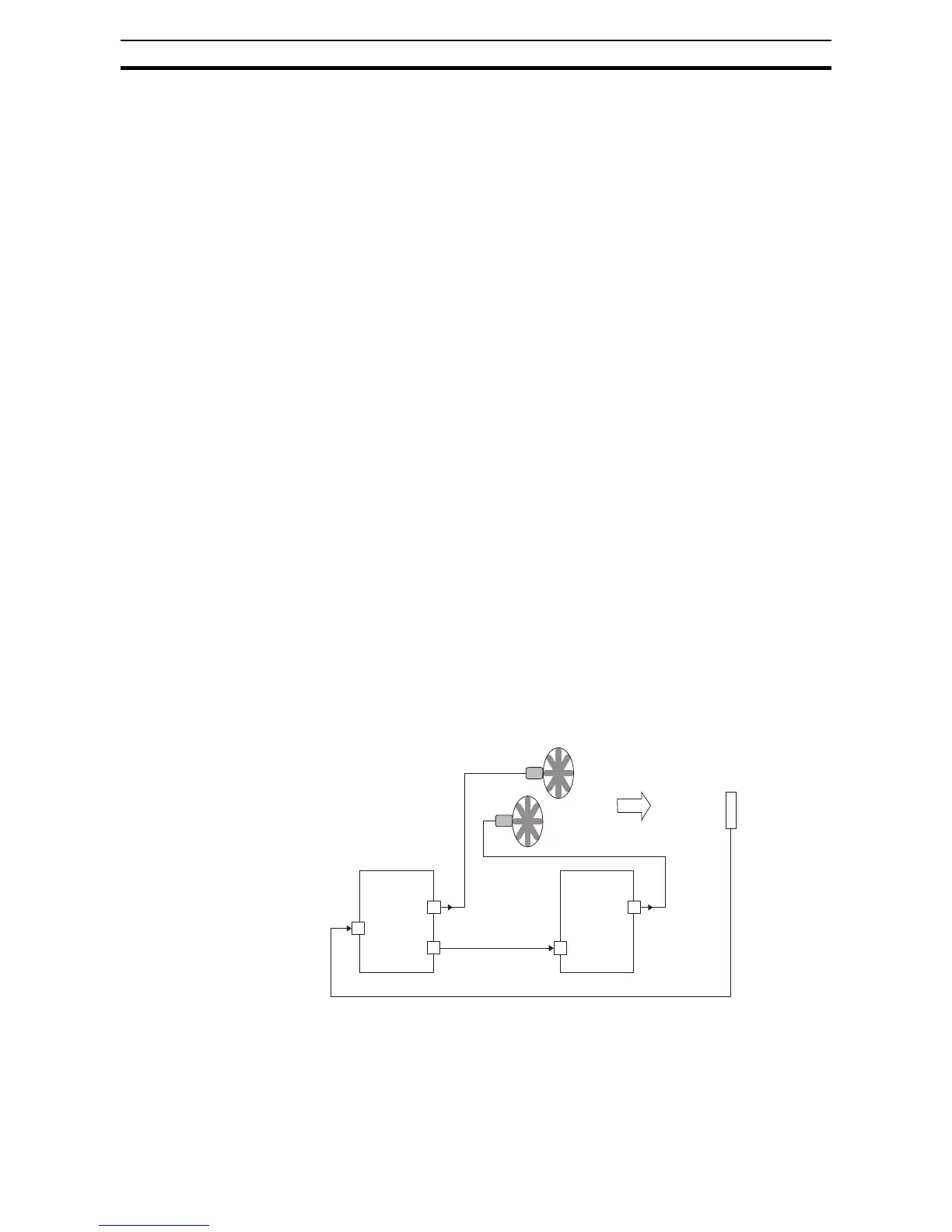
Refer to the example diagram below. Its two stages of control are defined as
follows:
• Stage 1 - Inverter #1 operating in PID loop mode, with motor driving a fan
• Stage 2 - Inverter #2 operating as an ON/OFF controller, with motor driv-
ing a fan
Stage #1 provides the ventilation needs in a building most of the time. On
some days, there is a change in the building's air volume because large ware-
house doors are open. In that situation, Stage #1 alone cannot maintain the
desired air flow (PV sags under SP). Inverter #1 senses the low PV and its
PID Second Stage Output at [FBV] terminal turns ON. This gives a Run FWD
command to Inverter #2 to provide the additional air flow.
Stage #1
Inverter #1 Inverter #2
[U, V, W] [U, V, W]
[O or [OI]]
[FBV] [FW]
PV
PID Second
Stage Output
Fan #1
Fan #2
Stage #2
Air flow Sensor
Process Variable