225
Analog Output Operation Section 4-8
1. Frequency Command by pulse train input
When using this mode, you should set
A001
to
06
. In this case the frequency is
detected by input-capture, and calculated based on the ratio of designated max.
frequency (under 32 kHz). Only an input terminal "EA" will be used in this case.
2. Using for process variable of PID control
You can use the pulse train input for process variable (feedback) of PID control.
In this case you need to set
A076
to
03
. Only "EA" input terminal is to be used
.
3. Simple positioning by pulse train input
This is to use the pulse train input like an encoder signal. You can select three
types of operation.
4-8 Analog Output Operation
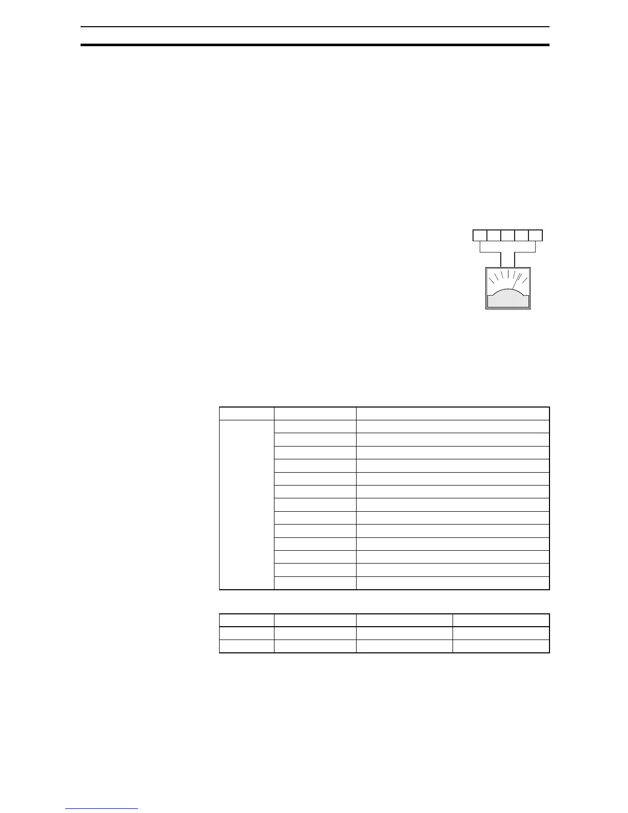
In inverter applications it is useful to monitor the
inverter operation from a remote location or from
the front panel of an inverter enclosure. In some
cases, this requires only a panel-mounted volt
meter. In other cases, a controller such as a PLC
may provide the inverter's frequency command,
and require inverter feedback data (such as output
frequency or output current) to confirm actual oper-
ation. The analog output terminal [AM] serves
these purposes.
The inverter provides an analog voltage output on terminal [AM] with terminal
[L] as analog GND reference. The [AM] can output inverter frequency or cur-
rent output value. Note that the voltage range is 0 to +10 V (positive-going
only), regardless of forward or reverse motor rotation. Use
C028 to configure
terminal [AM] as indicated below.
The [AM] signal offset and gain are adjustable, as indicated below.
Func. Code Description
C028 00 Inverter output frequency
01 Inverter output current
02 Inverter output torque
03 Digital output freqnency
04 Inverter output goltage
05 Inverter input power
06 Electronic Thermal Load
07 LAD frequency
08 Digital current monitor
10 Cooling fin temperature
12 General purpose
15 Pulse train
16 Option
Func. Description Range Default
C106 [AM] output gain 50~200 100.
C109 [AM] output offset 0~100 0.0
AM H O OI L
+-