333
Appendix E
Safety (ISO 13849-1)
E-1 Introduction
The Gate Suppress function can be utilized to perform a safe stop according
to the EN60204-1, stop category 0 (Uncontrolled stop by power removal). It is
designed to meet the requirements of the ISO13849-1, PL=d.
E-2 How it works
Removing the voltage from both terminals GS1 and GS2 disables the drive
output, i.e. the power supply to the motor is cut by stopping the switching of
the output transistors in a safe way. EDM output is activated when GS1 and
GS2 is given to the drive.
Always use both inputs to disable the drive. If for any reason only one channel
is opened, the drive output is stopped too but the EDM output is not activated.
In this case the Safe Disable input wiring must be checked.
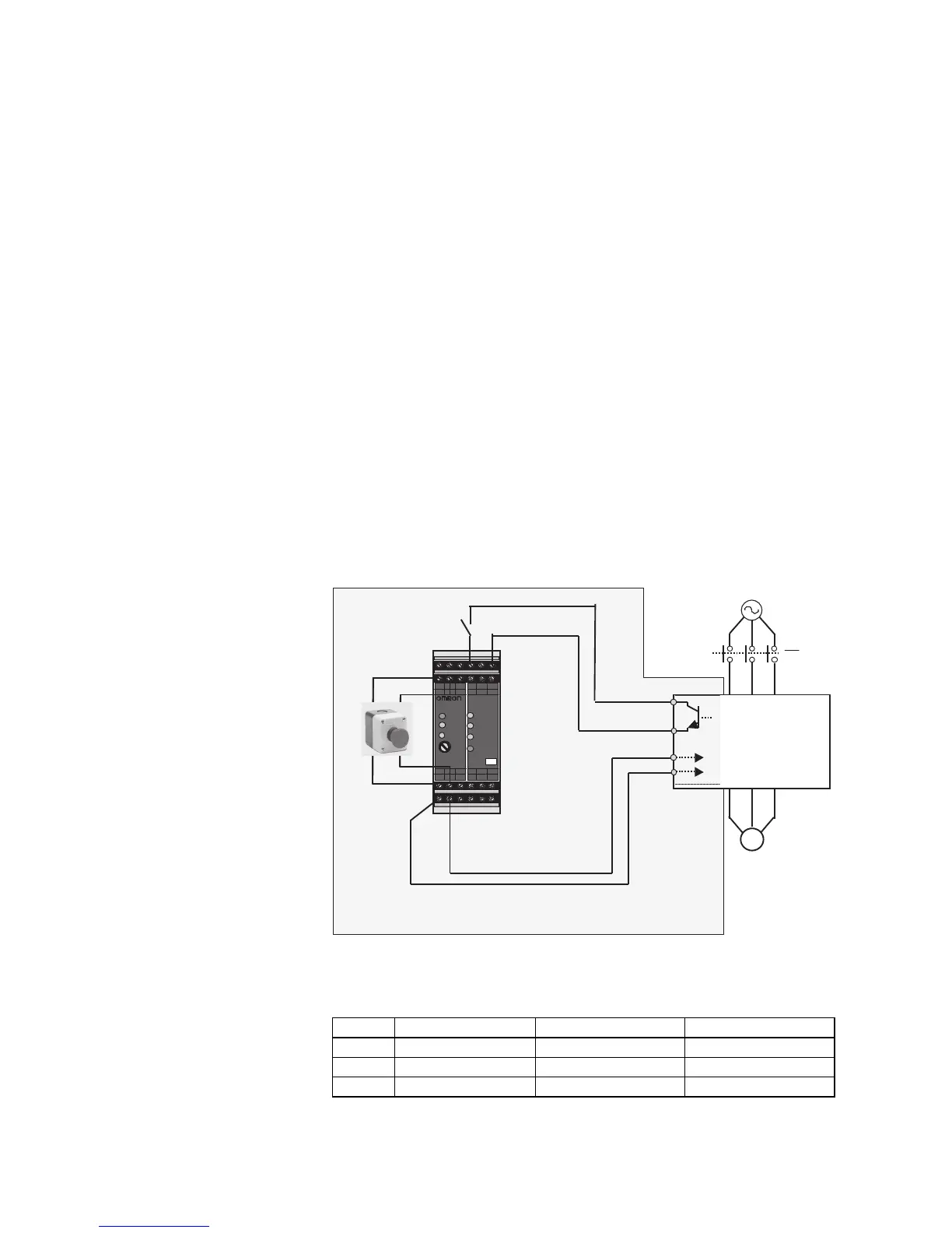
E-3 Installation
When the Gate Suppress function is utilized, connect the drive to a safety
certified interrupting device utilizing EDM output signal to reconfirm both
safety inputs GS1 and GS2. Follow the wiring instructions in the user manual
chapter 3.
E-4 Components to be combined
Followings are the example of the safety devices to be combined.
Series Model Norms to comply reference certificate
GS9A 301 ISO13849-2 cat4, SIL3 06.06.2007
G9SX GS226-T15-RC IEC61508 SIL1-3 04.11.2004
NE1A SCPU01-V1 IEC61508 SIL3 27.09.2006