97
"A" Group: Standard Functions Section 3-5
Refer to parameter A011 to A015 for analog voltage input.
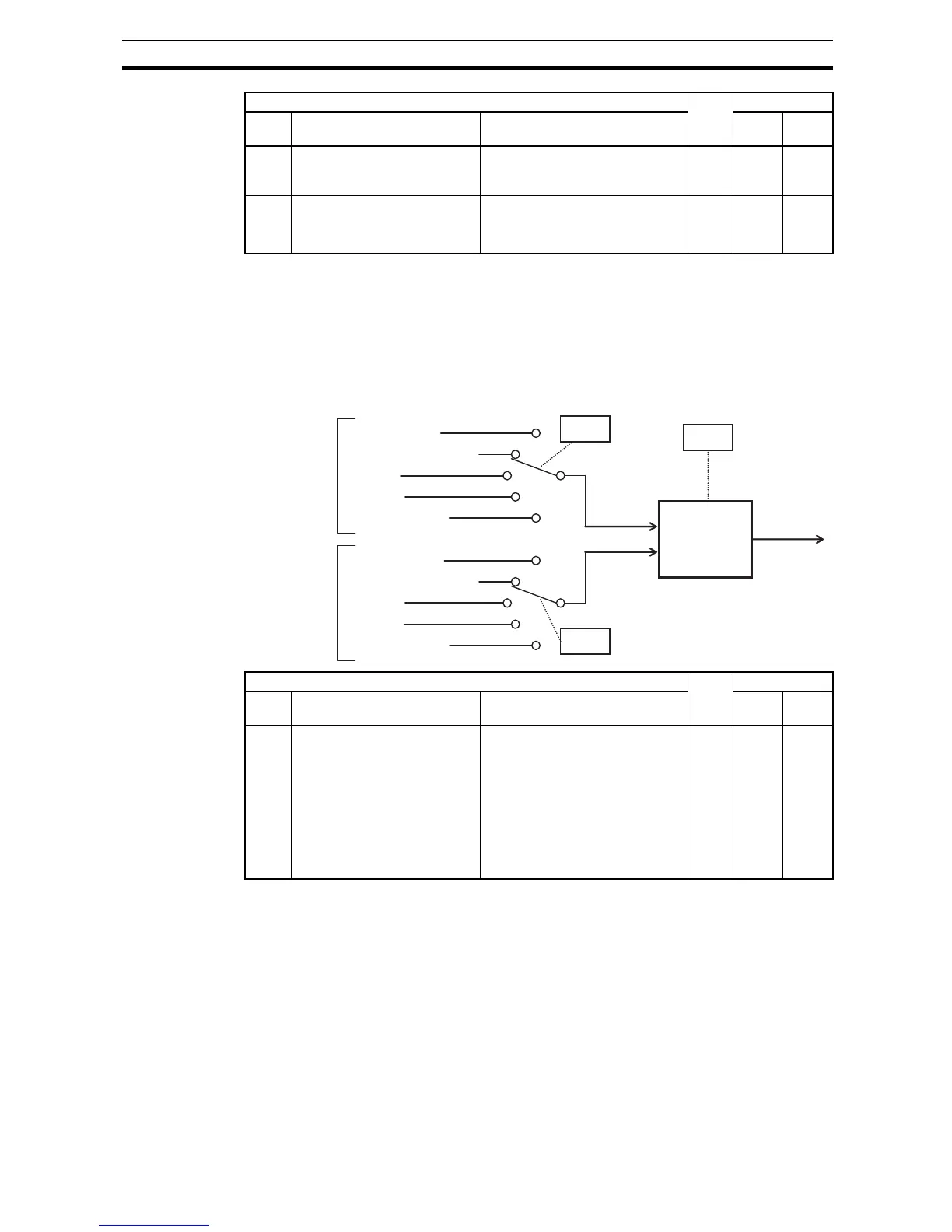
Analog Input Calculate Function - The inverter can mathematically combine
two input sources into one value. The Calculate function can either add, sub-
tract, or multiply the two selected sources. This provides the flexibility needed
by various applications. You can use the result for the output frequency setting
(use A001=10) or for the PID Process Variable (PV) input (use A075=03).
A104 [OI] input active range end cur-
rent
The ending point (offset) for the
current input range, range is 0. to
100.%
8 100. %
A105 [OI] input start frequency
select
Two options; select codes:
00... Use offset (A101 value)
01... Use 0 Hz
8 00 –
*1
Up to 1000Hz for High frequency mode (d060 set to "2")
*2
Up to 1000Hz for High frequency mode (d060 set to "2")
"A" Function Run
Mode
Edit
Defaults
Func.
Code
Name Description EU Units
Digital operator
Remote operator POT
[O] input
[OI] input
Network variable
A141
A input select
A142
B input select
•
A + B
•
A - B
•
A * B
A
B
A143
Digital operator
[O] input
[OI] input
Network variable
“CAL”
(result)
Remote operator POT
"A" Function Run
Mode
Edit
Defaults
Func.
Code
Name Description EU Units
A141 A input select for calculate
function
Seven options:
00... Operator
01... VR
02... Terminal [O] input
03... Terminal [OI] input
04... RS485
05... Option
07... Pulse train input
8 02 –