EasyManuals Logo

Omron MX2 User Manual

Omron MX2
356 pages
To Next Page IconTo Next Page
To Previous Page IconTo Previous Page
Page #272 background imageLoading...
Page #272 background image
250
Maintenance and Inspection Section 6-4
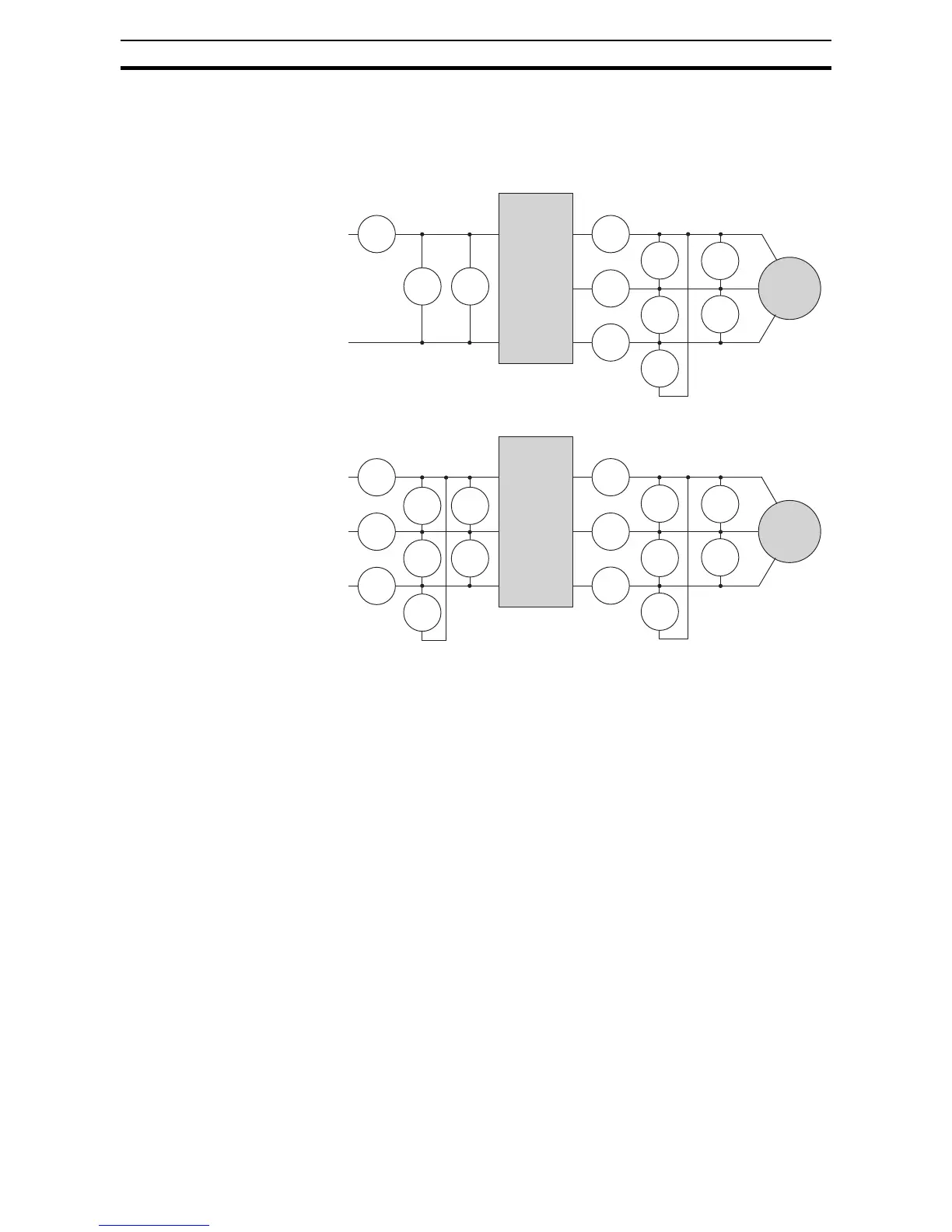
The figures below show measurement locations for voltage, current, and
power measurements listed in the table on the previous page. The voltage to
be measured is the fundamental wave effective voltage. The power to be
measured is the total effective power.
L1
N
T1
T2
T3
L1 U
V
W
I
1
I
1
E
U-V
E
U-V
E
U-V
I
1
I
1
N
E
1
W
1
W
01
W
02
Inverter
Motor
Single-phase Measurement Diagram
L1
L2
L3
T1
T2
T3
U
V
W
R
S
T
I
1
I
2
I
3
I
1
E
U-V
E
U-V
E
U-V
I
1
I
1
E
1
E
1
E
1
W0
1
W0
2
W
01
W
02
Inverter
Motor
Three-phase Measurement Diagram

Table of Contents

Other manuals for Omron MX2

Questions and Answers:

Question and Answer IconNeed help?

Do you have a question about the Omron MX2 and is the answer not in the manual?

Omron MX2 Specifications

General IconGeneral
ModelMX2
CategoryInverter
Enclosure RatingIP20
Control MethodV/f control, Sensorless vector control
Frequency Range0.1 to 400 Hz
ProtectionOvercurrent, Overvoltage, Undervoltage, Overheat, Short circuit
CommunicationModbus RTU
Ambient Temperature-10 to 50 °C (without freezing or condensation)
Overload Capacity150% for 60 seconds
Cooling MethodFan Cooled
Humidity5 to 95% RH (without condensation)
AltitudeUp to 1000m without derating
Voltage200-240 VAC, 380-480 VAC
Braking UnitBuilt-in (for certain models), Optional External

Related product manuals