200
Using Intelligent Output Terminals Section 4-6
4-6-4 Output Signal ON/OFF Delay Function
Intelligent outputs including terminals [11], and the output relay, have config-
urable signal transition delays. Each output can delay either the OFF-to-ON or
ON-to-OFF transitions, or both. Signal transition delays are variable from 0.1
to 100.0 seconds. This feature is useful in applications that must tailor inverter
output signals to meet timing requirements of certain external devices.
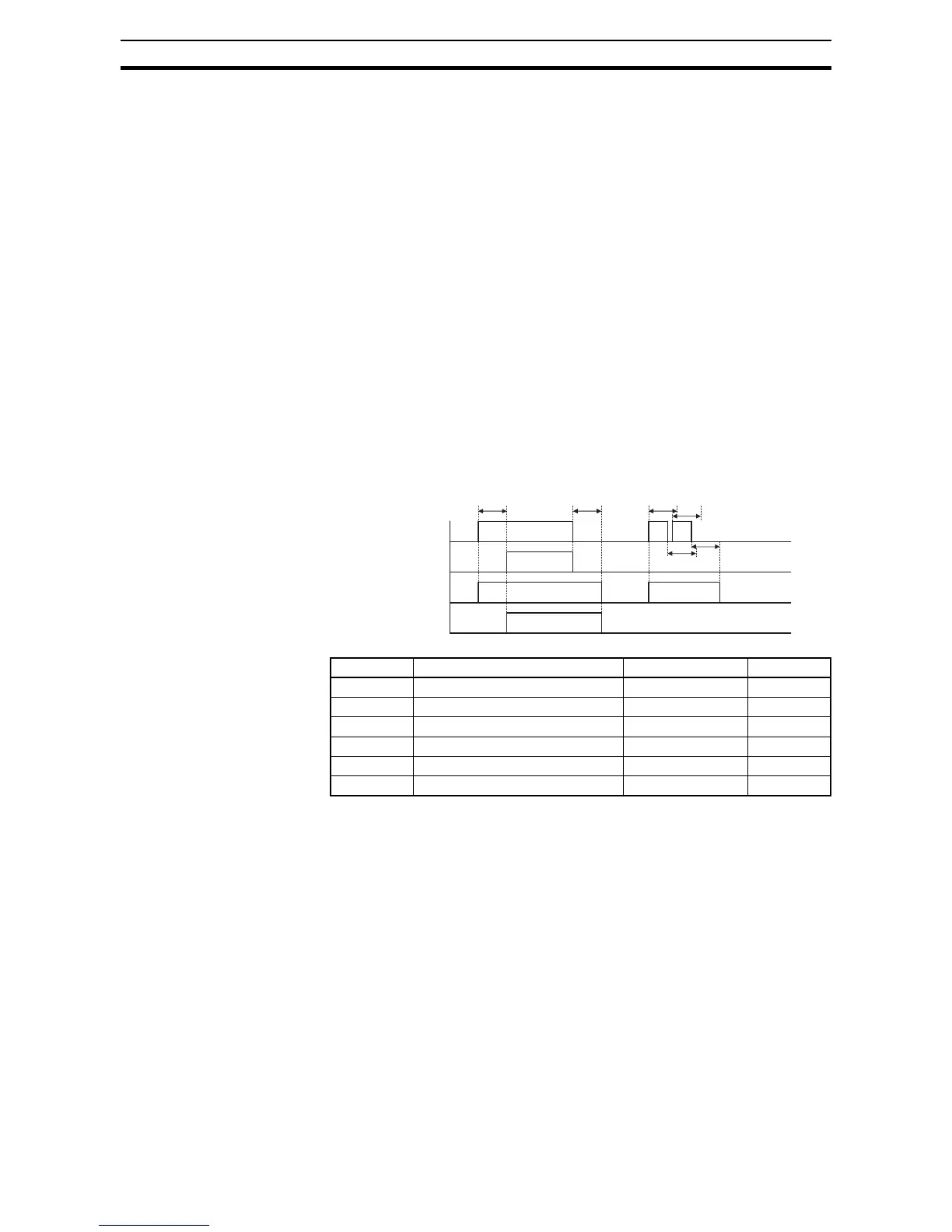
The timing diagram below shows a sample output signal (top line) and the
results of various ON/OFF delay configurations.
• Original signal – This example signal waveform consists of three sepa-
rate pulses named "A," "B," and "C."
•...with ON delay – Pulse A is delayed by the duration of the ON delay
time. Pulses B and C do not appear at the output, because they are
shorter than the ON delay.
• ...with OFF delay – Pulse A is lengthened by the amount of the OFF
delay time. The separation between pulses B and C does not appear at
the output, because it is shorter than the OFF delay time.
• ...with ON/OFF delays – Pulse A is delayed on both leading and trailing
edges by the amounts of the ON and OFF delay times, respectively.
Pulses B and C do not appear at the output, because they are shorter
than the ON delay time.
Use of the ON/OFF signal delay functions are optional. Note that any of the
intelligent output assignments in this section can be combined with ON/OFF
signal timing delay configurations.
Func. Description Range Default
C130 Output [11] ON delay 0.0 to 100.0 sec. 0.0
C131 Output [11] OFF delay 0.0 to 100.0 sec. 0.0
C132 Output [12] ON delay 0.0 to 100.0 sec. 0.0
C133 Output [12] OFF delay 0.0 to 100.0 sec. 0.0
C140 Output relay ON delay 0.0 to 100.0 sec. 0.0
C141 Output relay OFF delay 0.0 to 100.0 sec. 0.0
…with OFF delay
1
0
t
…with ON/OFF delays
1
0
…with ON delay
1
0
Original (no delays)
1
0
Output Signals:
ON
delay
OFF
delay
ON
delays
OFF
delays
CB A