283
ModBus Data Listing Section B-4
B-4-2 ModBus Holding Registers
The following tables list the holding registers for the inverter interface to the
network. The table legend is given below.
• Function Code – The inverter's reference code for the parameter or func-
tion (same as inverter keypad display)
• Name – The standard functional name of the parameter or function for
the inverter
• R/W – The read-only(R) or read-write access(R/W) permitted to the data
in the inverter
• Description – How the parameter or setting works (same as Chapter 3
description).
• Reg. – The network register address offset for the value. Some values
have a high-byte and low-byte address.
• Range – The numerical range for the network value that is sent and/or
received
!Tip The network values are binary integers. Since these values cannot have an
embedded decimal point, for many parameters it represents the actual value
(in engineering units) multiplied by a factor of 10 or 100. Network communica-
tions must use the listed range for network data. The inverter automatically
divides received values by the appropriate factor in order to establish the dec-
imal point for internal use. Likewise, the network host computer must apply
the same factor when it needs to work in engineering units. However, when
sending data to the inverter, the network host computer must scale values to
the integer range listed for network communications.
• Resolution – This is the quantity represented by the LSB of the network
value, in engineering units. When the network data range is greater than
the inverter's internal data range, this 1-bit resolution will be fractional.
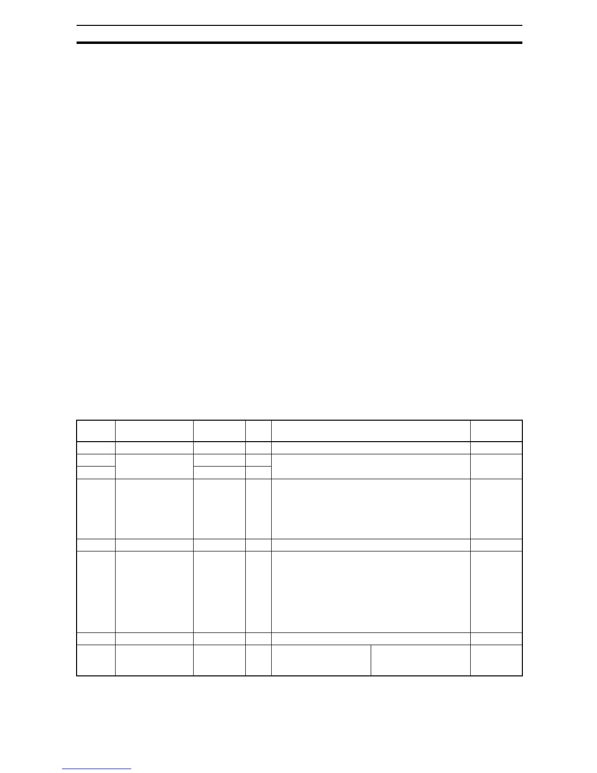
Register
No.
Function name Function
code
R/W Monitoring and setting items Data
resolution
0000h unused – – Inaccessible
0001h Frequency source F001 (high) R/W 0 to 40000 (valid when A001 = 03) 0.01 [Hz]
0002h F001 (low) R/W
0003h Inverter status A – R 0: Initial status
2: Stopping
3: Running
4: Free-run stop
5: Jogging
6: DC braking
7: Retrying
8: Tripping
9: Undervoltage (UV),
–
0004h Inverter status B – R 0: Stopping, 1: Running, 2: Tripping –
0005h Inverter status C – R 0: –
1: Stopping
2: Decelerating
3: Constant-speed opera-
tion
4: Accelerating
5: Forward rotation
6: Reverse rotation
7: Switching from fwd.
to rev. rotation,
8: Switching from rev.
to fwd. rotation,
9: Starting fwd.
10: Starting rev.
–
0006h PID feedback – R/W 0 to 10000 0.01 [%]
0007h
to
0010h
(Reserved) – R – –