230
Dynamic Braking Section 5-3
cause the inverter DC bus voltage to rise, resulting in an over-voltage trip. In
many applications, the over-voltage condition serves as a warning signal that
we have exceeded the deceleration capabilities of the system. The MX2
inverters have a built-in braking chopper, which sends the regenerative energy
from the motor during deceleration to the optional braking resistor(s). external
braking units may also be used if higher braking torques and/or duty cycles
are required. The dynamic braking resistor serves as a load, developing heat
to stop the motor just as brakes on an automobile develop heat during brak-
ing.
The braking resistor is the main component of a braking resistor assembly
that includes a fuse and thermal relay activated alarm relay for safety. And
switching circuit and power resistor are the main components of the dynamic
braking unit that includes a fuse and thermally activated alarm relay for safety.
However, be careful to avoid overheating its resistor. The fuse and thermal
relay are safeguards for extreme conditions, but the inverter can maintain
braking usage in a safe zone.
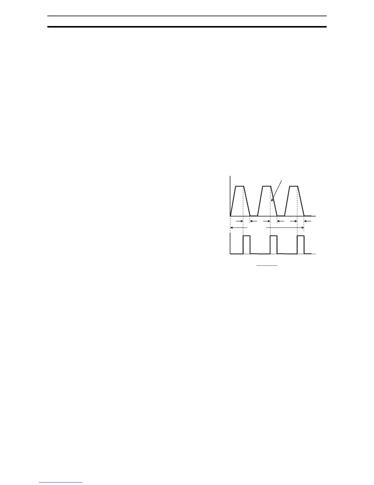
5-3-2 Dynamic Braking Usage
The inverter controls braking via a
duty cycle method (percent of the
time braking is ON versus total
time). Parameter b090 sets the
dynamic braking usage ratio. In the
graph to the right, the example
shows three uses of dynamic brak-
ing in a 100-second period. The
inverter calculates the average per-
centage usage in that time (T%).
The percentage of usage is propor-
tional to the heat dissipated. If T%
is greater than the b090 parameter
setting, the inverter enters the trip
mode and turns off the frequency
output.
Please note the following:
• When b090 is set for 0%, dynamic braking is not performed
• When the T% value exceeds the limit set by b090, dynamic braking ends.
• When mounting an external dynamic braking unit, set the usage ratio
(b090) to 0.0 and remove the external resistors.
• The cable from the external resistor to the inverter must not exceed 5 m
length.
• The individual wires from the resistor to the inverter must not be bundled
together.
5-3-3 Braking Resistor Selection Tables
The MX2 series inverters have integrated braking units (chopper). Stopping
torque is available by adding external resistors. The required braking torque
depends on your particular application. Next table helps you to choose the
right resistor for 3% and 10% braking duty applications (ocasional braking).
To achieve higher duty cycles, external braking units (separate chopper with
higher capacity) are required. Check with your supplier.
Output freq.
Tc (100s)
t
1
t
Dynamic braking
t
2
t
3
Regen.
t
b090 T%=
100
100 sec
321
×
++ ttt