EasyManuals Logo

Omron MX2 User Manual

Omron MX2
356 pages
To Next Page IconTo Next Page
To Previous Page IconTo Previous Page
Page #352 background imageLoading...
Page #352 background image
330
CE-EMC Installation Guidelines Section D-1
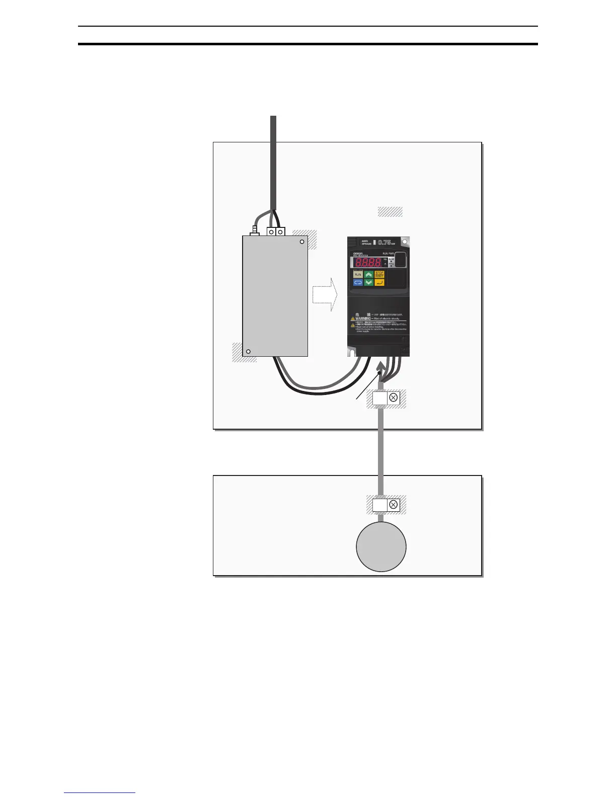
D-1-2 Installation for MX2 series
Model 3-ph. 200 V class and 3-ph. 400 V class are the same concept for the
installation.
*) Both earth portions of the shielded cable must be connected to the earth
point by cable clamps.
Input choke or equipment to reduce harmonic current is necessary for CE
marking (IEC 61000-3-2 and IEC61000-3-4) from the harmonic current point
of view, even conducted emission and radiated emission passed without the
input choke.
Shielded cable
Power supply
1-ph. 200 V
Motor
3~
U,V,W
Metal plate (earth)
Earth line is connected to the
heatsink of the inverter
(or PE terminal for bigger models)
PE
EMC filter
(Foot-print)
Cable clamp *
The filter is a footprint type, so it is located
between the inverter and the metal plate.
Remove the insulation material coating of the
earth contact portions so to obtain good
grounding condition.
Cable clamp *
Metal plate (earth)
L1,N

Table of Contents

Other manuals for Omron MX2

Questions and Answers:

Question and Answer IconNeed help?

Do you have a question about the Omron MX2 and is the answer not in the manual?

Omron MX2 Specifications

General IconGeneral
ModelMX2
CategoryInverter
Enclosure RatingIP20
Control MethodV/f control, Sensorless vector control
Frequency Range0.1 to 400 Hz
ProtectionOvercurrent, Overvoltage, Undervoltage, Overheat, Short circuit
CommunicationModbus RTU
Ambient Temperature-10 to 50 °C (without freezing or condensation)
Overload Capacity150% for 60 seconds
Cooling MethodFan Cooled
Humidity5 to 95% RH (without condensation)
AltitudeUp to 1000m without derating
Voltage200-240 VAC, 380-480 VAC
Braking UnitBuilt-in (for certain models), Optional External

Related product manuals