Section 26: XLII SLIDE-OUT
PA1553
37
The manual override procedures consist in
rotating the slide-out motor shaft extension using
a cordless power drill with a 3/8" hexagonal bit.
However, it is very important to follow all the
instructions very carefully to assure that the
inflatable seal or the retraction mechanisms are
not damaged.
18.1 PRELIMINARY CONDITIONS
FOR MANUAL OVERRIDE
PROCEDURE
Before using the slide-out manual override
procedures, make sure that the problem cannot
be solved by one of the following simple checks:
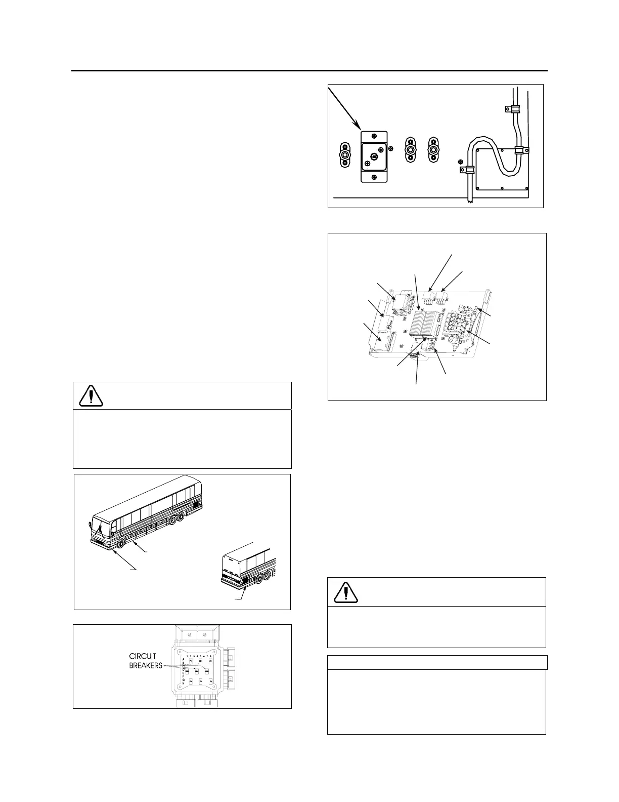
• Make sure that none of the breakers are
tripped (the breakers are located inside the
VEC on the slide-out control panel (FIGURE
88) and the main slide-out breaker is located
in the engine R.H. side access compartment
(FIGURE 89)).
• Make sure the barking brake is applied and
that transmission is in the "NEUTRAL"
position.
• Make sure the voltage is high enough by
running the engine at fast idle or having the
battery charger connected.
CAUTION
Before extending or retracting the slide-out,
always open a window to avoid movement
restriction and to prevent the motor from
stopping in overcurrent because of a vacuum
or pressure build up inside the vehicle.
FRONT SERVICE
COMPARTMENT
SLIDE-OUT CONTROL
PANEL INSIDE
ENGINE R.H. SIDE ACCESS
COMPARTMENT
FIGURE 87: COMPARTMENTS LOCATION
FIGURE 88: VEC CIRCUIT BREAKERS ON SLIDE-OUT
CONTROL PANEL
SLIDE-OUT
BREAKER
FIGURE
89: MAIN SLIDE-OUT BREAKER IN ENGINE R.H.
SIDE ACCESS COMPARTMENT
PNEUMATIC
COMPONENT
PANEL
PRESSURE
TRANSDUCER
SLIDE-OUT VEC
MASTER ID
CECM
FRONT SLIDE-OUT
I/O-B MODULE
FRONT SLIDE-OUT MOTOR
HIGH CURRENT RELAY (+)
REAR SLIDE-OUT MOTOR
HIGH CURRENT RELAY (+)
REAR SLIDE-OUT
I/O-B MODULE
FRONT SLIDE-OUT MOTOR
HIGH CURRENT RELAY (-)
REAR SLIDE-OUT MOTOR
HIGH CURRENT RELAY (-)
FIGURE
90: SLIDE-OUT CONTROL PANEL
18.1.1 Manual retracting procedure –
Front and rear slide-out
1. Turn the ignition switch to the "OFF"
position, and remove the ignition key for
more safety.
2. Deflate the inflatable seal by using the
relieving shut-off valve located on the
pneumatic component panel (FIGURE 91).
3. Turn the handle clockwise to deflate the
seal. Make sure the pressure indicator
reading is "0 psi".
CAUTION
The pressure in the inflatable seal must be
completely relieved to prevent any damage to
the seal.
NOTE
When air pressure is relieved using the shut-
off valve, the normal extending and retracting
operation cycle is disabled, for that reason the
slide-out cannot be moved using the handheld
control.
 Loading...


