Measurements and Results
R&S
®
FSW
234User Manual 1173.9411.02 ─ 43
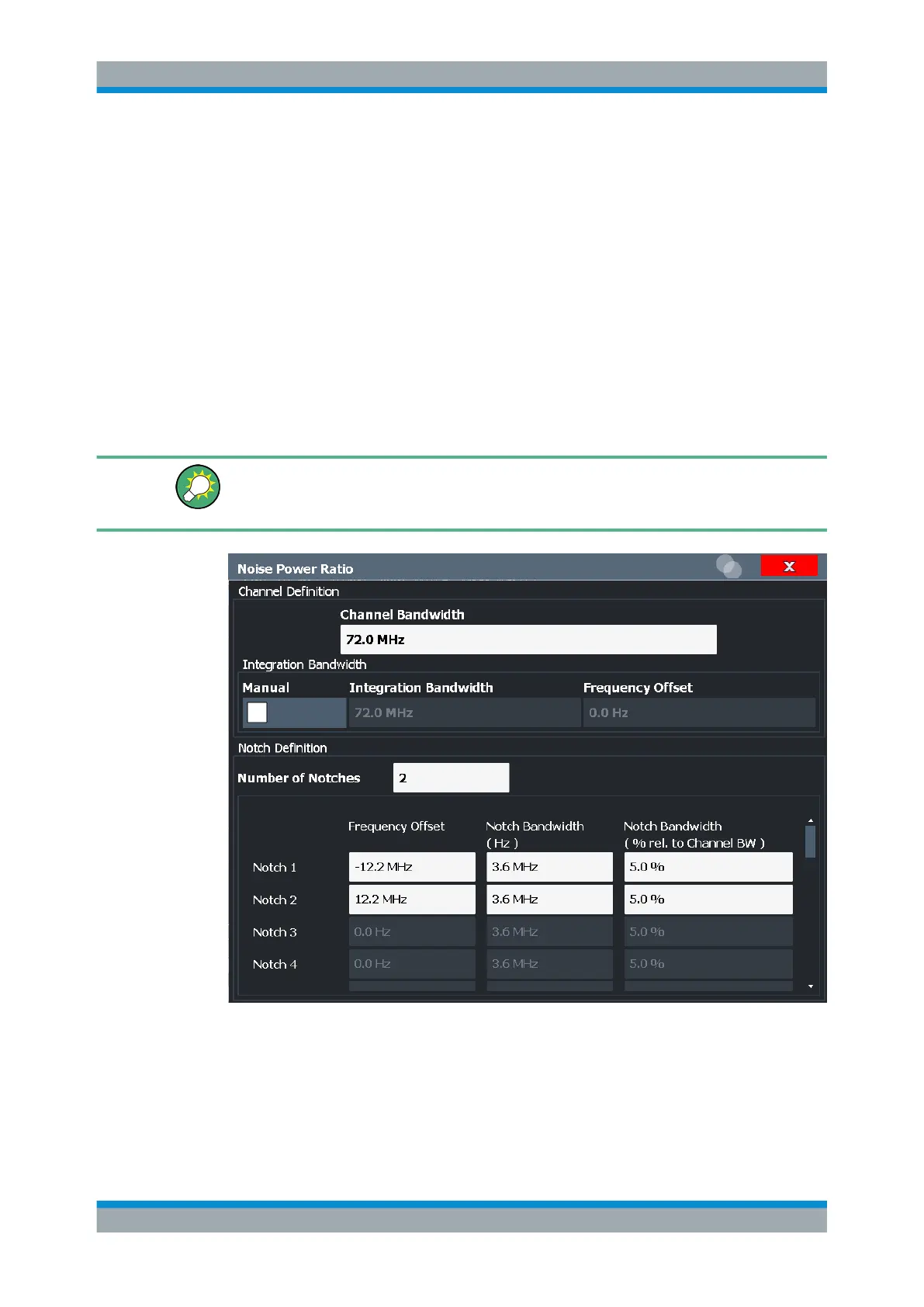
9. For each notch, define the bandwidth (absolute or relative to the channel band-
width) and its position (relative to the center frequency).
The channel and notches are indicated in the spectrum diagram, and the power
results are indicated in the result summary.
7.5.8 Measurement Example
Assume a satellite channel with a bandwidth of 72 MHz at a center frequency of
500 MHz. Notch filters are located around the subcarrier frequencies 487.8 MHz and
512.2 MHz, with a bandwidth of 3.6 MHz.
We will demonstrate how to determine the distortion caused by each subcarrier on the
other, defined as the noise power ratio for each notch.
How to perform this measurement in a remote environment is described in Chap-
ter 14.5.6.5, "Programming Example: Measuring the Noise Power Ratio",
on page 916.
1. From the "Overview", select "Frequency".
2. Define the "Center Frequency" = 500
MHz.
3. Define a "Span" = 80
MHz.
4. From the "Overview", select "Select Measurement".
Noise Power Ratio (NPR) Measurement

 Loading...


