Common Measurement Settings
R&S
®
FSW
364User Manual 1173.9411.02 ─ 43
other connected devices. Using the same trigger on several devices is useful to syn-
chronize the transmitted and received signals within a measurement.
For details on the connectors see the R&S FSW "Getting Started" manual.
External trigger as input
If the trigger signal for the R&S FSW is provided by an external device, the trigger sig-
nal source must be connected to the R&S FSW and the trigger source must be defined
as "External" in the R&S FSW.
External triggers with R&S FSW-B2000/B5000
When the input is provided from an R&S FSW with the B2000/B5000 option, the con-
nected oscilloscope samples the data. Thus, triggering is also processed by the oscillo-
scope. The trigger source can be either the IF level or an external trigger, for example
from the R&S FSW.
In this case, the trigger source must be defined as "External CH3" (or "External Ana-
log" for power splitting mode) on the R&S FSW.
Trigger output
The R&S FSW can provide output to another device either to pass on the internal trig-
ger signal, or to indicate that the R&S FSW itself is ready to trigger.
The trigger signal can be output by the R&S FSW automatically, or manually by the
user. If it is provided automatically, a high signal is output when the R&S FSW has trig-
gered due to a sweep start ("Device Triggered"), or when the R&S FSW is ready to
receive a trigger signal after a sweep start ("Trigger Armed").
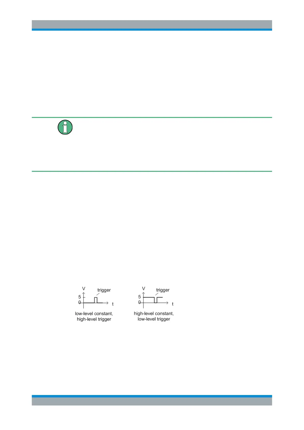
Manual triggering
If the trigger output signal is initiated manually, the length and level (high/low) of the
trigger pulse is also user-definable. Note, however, that the trigger pulse level is always
opposite to the constant signal level defined by the output "Level" setting, e.g. for
"Level" = "High", a constant high signal is output to the connector until the "Send Trig-
ger" button is selected. Then, a low pulse is provided.
8.2.1.3 IF and Video Signal Output
The measured IF signal or displayed video signal (i.e. the filtered and detected IF sig-
nal) can be provided at the IF/VIDEO/DEMOD or "IF OUT 2 GHz/ IF OUT 5 GHz" out-
put connector.
Data Input and Output

 Loading...


