Common Measurement Settings
R&S
®
FSW
489User Manual 1173.9411.02 ─ 43
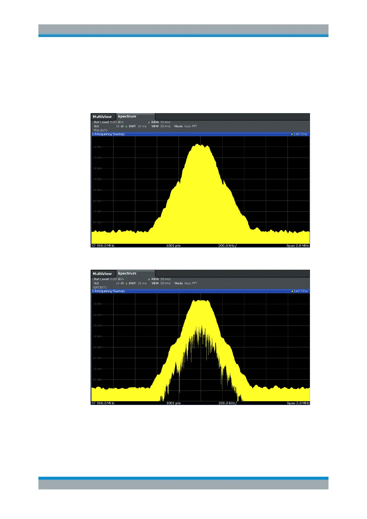
Example:
By using a gate in sweep mode and stopping the measurement while the gate signal is
inactive, the spectrum for pulsed RF carriers can be displayed without the superposi-
tion of frequency components generated during switching. Similarly, the spectrum can
also be analyzed for an inactive carrier. The sweep can be controlled by an external
gate or by the internal power trigger.
Figure 8-31: GSM signal with GATE OFF
Figure 8-32: GSM signal with GATE ON
Gated sweep operation is also possible for zero span measurements. This allows you
to display level variations of individual slots, for instance in burst signals, versus time.
Trigger and Gate Configuration

 Loading...


