Getting Started
R&S
®
FSW
61User Manual 1173.9411.02 ─ 43
5.2.2.13 AUX PORT
The 9-pole SUB-D male connector provides control signals for controlling external
devices. The voltage levels are of the TTL type (max. 5 V).
Pin Signal Description
1 +5 V / max. 250 mA Supply voltage for external circuits
2 to 7 I/O Control lines for user ports (see User manual)
8 GND Ground
9 READY FOR TRIGGER Signal indicating that the instrument is ready to
receive a trigger signal (Low active = 0 V)
Short-circuit hazard
Always observe the designated pin assignment. A short-circuit can damage the port.
5.2.2.14 GPIB Interface
The GPIB interface is in compliance with IEEE488 and SCPI. A computer for remote
control can be connected via this interface. To set up the connection, a shielded cable
is recommended. For more details, refer to "Setting Up Remote Control" in the User
Manual.
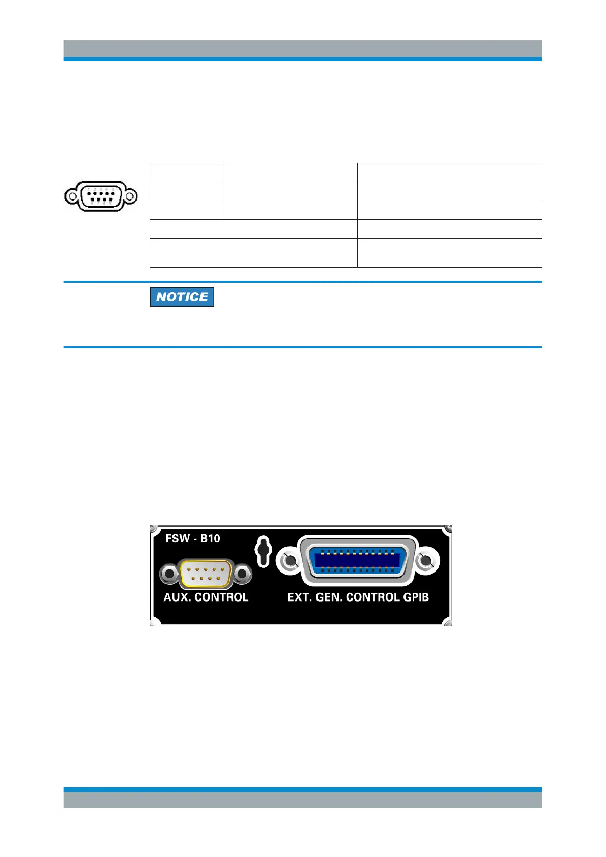
5.2.2.15 External Generator Control Option (R&S FSW-B10)
The external generator control option provides an additional GPIB and an "AUX con-
trol" connector.
The GPIB connector can be used to connect the external generator to the R&S FSW.
The female "AUX control" connector is required for TTL synchronization, if supported
by the generator.
For details on connecting an external generator, see the "External Generator Control"
section of the R&S FSW User Manual.
Instrument Tour

 Loading...


