Rockwell Automation Publication 2198-UM002L-EN-P - October 2021 209
Chapter 6 Configure and Start the Kinetix 5700 Drive System
The Safety Network Number (SNN) field populates automatically when
the Connection mode includes an integrated Motion and Safety or
Safety-only connection. For a detailed explanation of the safety network
number, refer to the appropriate GuardLogix controller publication as
defined in Additional Resources
on page 13.
6. Click OK to close the Module Definition dialog box.
7. Click Apply.
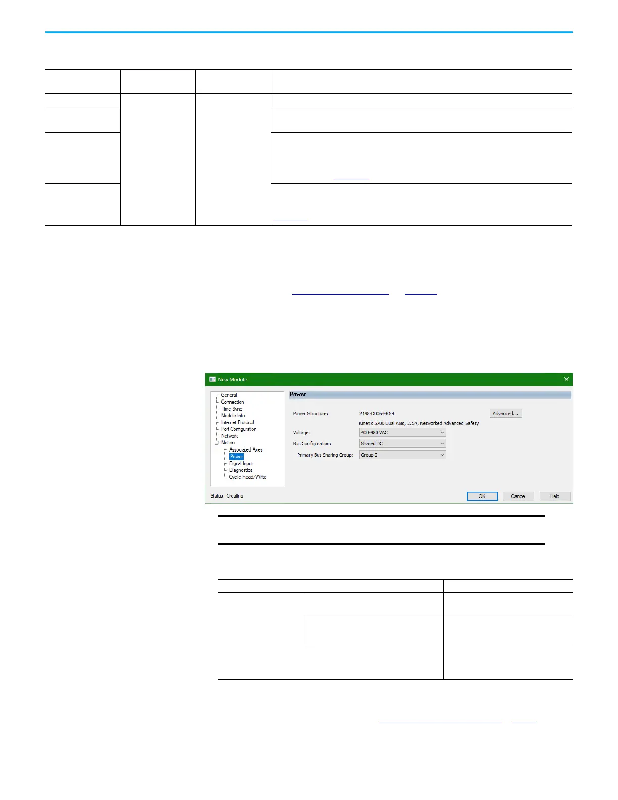
Configure the Power and Safety Categories
1. Click the Power category.
2. From the pull-down menus, choose the power options appropriate for
your hardware configuration.
Table 120 - Motion Safety Definitions
Motion Safety Mode
Safety Application
Mode
Module Connection
Options
Description
STO Only
Networked
• Motion and Safety
•Safety Only
2198-xxxx-ERS3 (series A and B): STO function only.
Safe Stop Only -
No Feedback
•2198-xxxx-ERS4: STO function and Timed SS1 Safe Stop functions are available.
•2198-xxxx-ERS3 (series B): STO function and Timed SS1 Safe Stop functions are available.
Single Feedback
Monitoring
Primary feedback is used in the safety object for safe monitoring. The feedback can be a SIL
rated Hiperface DSL encoder, for example, a VPL-B1003P-Q or W motor used in the DSL Feedback
port. This can also be a Sine/Cosine or EnDat device, for example, an MPL-B310P-M motor used in
the Universal Feedback port. See the Kinetix 5700 Safe Monitor Functions Safety Reference
Manual, publication 2198-RM001
, to evaluate SIL levels possible with a single feedback device.
Dual Feedback
Monitoring
In addition to primary feedback, an external feedback device is used to improve SIL levels. For
example, the Bulletin 842HR type encoder can be used in the Universal Feedback port as a Sine/
Cosine device. See the Kinetix 5700 Safe Monitor Functions Safety Reference Manual, publication
2198-RM001
, to evaluate SIL levels possible with two feedback devices.
IMPORTANT
The Logix Designer application enforces shared-bus
configuration rules for Kinetix 5700 drives.
Attribute Menu Description
Bus Configuration
Shared DC
(1)
(1) Shared DC bus configuration is the default selection for single-axis and dual-axis inverters.
Applies to 2198-Sxxx-ERSx and
2198-Dxxx-ERSx inverter drives.
Shared DC - Non-CIP Motion™ Converter
(2)
(2) Because the 8720MC-RPS unit is not an EtherNet/IP network device the Logix 5000 controller does not communicate with it.
The designated inverter, configured as the Shared DC - Non-CIP Motion Converter, monitors the 8720MC-RPS unit status
through a digital input (Regen OK) and communicates with the other inverters to signal when the DC-bus voltage is present.
Applies to the designated inverter in
drive systems powered by the
8720MC-RPS regenerative power supply.
Bus Sharing Group
(3)
(2)
(3) For more information on bus-sharing groups, refer to Understand Bus-sharing Group Configuration on page 251.
•Group1
•Group2
•Group3…
Applies to any bus-sharing
configuration.

 Loading...


