Operation
Diesel engine
149 / 476
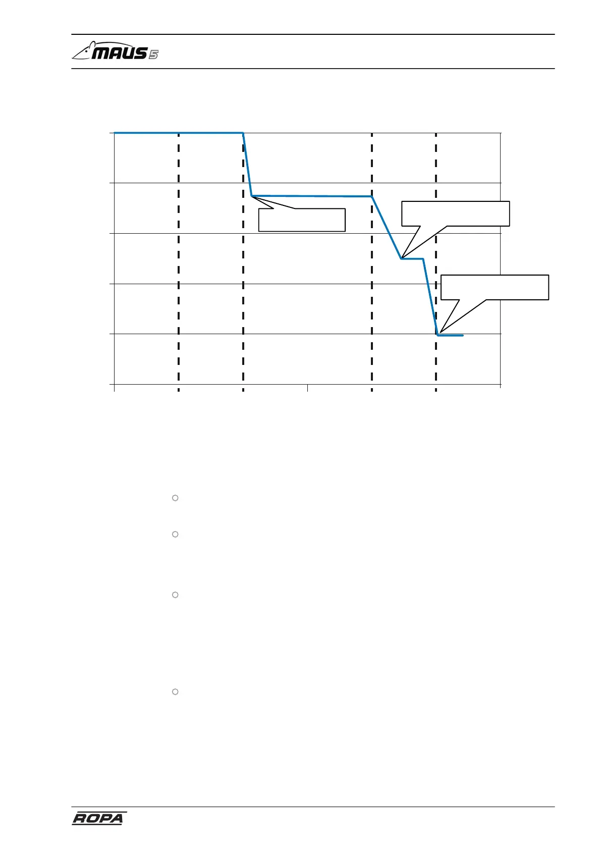
6.6.4.3 Power reduction process
Error detection Warning Slight reduction
(in 15 min.)
Time in minutes
Engine torque
Strong
Reduction
Full
Reduction
80%
60%
40%
20%
0%
100%
0 60 120 180 240
100% - 75% torque
100% - 60% nominal rotational speed (25 min.)
75% - 50% torque (1% / 25 min.)
60% -idling speed (10 min.)
50% - 20% torque (10 min.)
6.6.5 Modifications respectively additions to the engine operating
manual from Mercedes-Benz
The followings items listed below must generally be considered for the engines from
Mercedes-Benz, which are installed in ROPA machines:
The engine OM 936 LA 260kW and 1400 Nm is installed. This means that only a
part of the operating manual from Mercedes-Benz applies, namely those referring
to these engine models, and those parts generally applying to all engine models.
All engines are not fitted with a flame starter system, but with a constant throttle
brake. Control is performed using the CPC4 control device via CAN bus. This con-
trol device is located in the central electrical system. The exhaust after-treatment
system of the machine is controlled by ACM. This is located somewhat in the mid-
dle/left side of the machine frame over the rear side of transmission.
The "Warning lamp electronics" and the "Stop lamps" mentioned in the operat-
ing manual from MTU/Mercedes-Benz are replaced by warning indications on the
R-Touch for the ROPA machines. But the meaning for these indications is iden-
tical to the lamps described in the operating manual from MTU/Mercedes-Benz.
As soon as the STOP indication is displayed on the R-Touch, the engine must be
IMMEDIATELY shut off, because there is a severe engine fault, which may lead to
an engine breakdown in case of further operation. The control lamp "Charging cur-
rent" is also replaced by a warning indication on the R-Touch for ROPA machines.
The diagnosis socket (X-340 (1)) for the engine electronics is located in the front/
top of the central electrical system.