Section 04 ENGINE (2-STROKE)
Subsection 07 (EXHAUST SYSTEM)
947 Engines
CAUTION: Torque wrench tightening specifi-
cations must be strictly adhered to. Locking
devices (ex.: locking tabs, elastic stop nuts,
self-locking fasteners, etc.) must be installed
or replaced with new ones where specified. If
the efficiency of a locking device is impaired, it
must be renewed.
NOTE: Loosen all pipe supports from engine be-
fore installing tuned pipe.
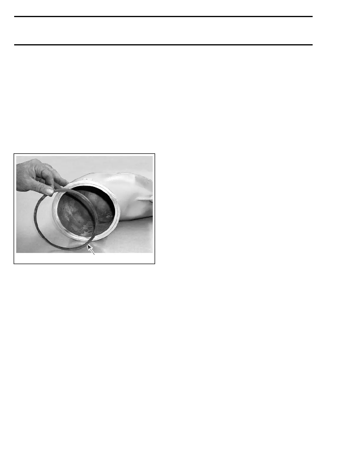
Make sure to install the sealing ring no. 15 on
tunedpipeconeifitwasremoved.
F07D0RA
1
TYPICAL
1. Sealing ring
Apply a thin layer of Loctite 30542 heat resistant
sealant (P/N 293 800 090) all around sealing ring
no. 15.
CAUTION: Damage to bushings and/or sleeve
will eventually cause stress to tuned pipe and
may cause cracking.
CAUTION: It is very important that the threads
are free of debris before installing new self-
locking fasteners. Refer to removal procedure
for the proper thread cleaning procedure.
Clean the “Y” manifold and tuned pipe surfaces.
Screw stud no. 21 into the “Y” manifold. Torque
to 47 N•m(35lbf•ft).
Install the new bushing no. 18.
Torquing Sequence
CAUTION: Torque the tuned pipe in accordance
with the following sequence, otherwise serious
engine damage may occur.
NOTE: Apply Loctite 243 (P/N 293 800 060) on
stud nut before tightening to 2.5 N•m(22lbf•in).
Use special tool (P/N 529 035 505).
Install external seal no. 22 andsecurewithalock-
ing tie.
178 smr2004-Complete Line Up

 Loading...


