Section 05 ENGINE (4-TEC)
Subsection 03 (EXHAUST SYSTEM)
F19D04A
Inspection
Inspect parts condition paying attention for defor-
mation, cracks or other damage. Check hoses.
Replace any defective part.
Installation
Installation is the reverse of the removal proce-
dures.
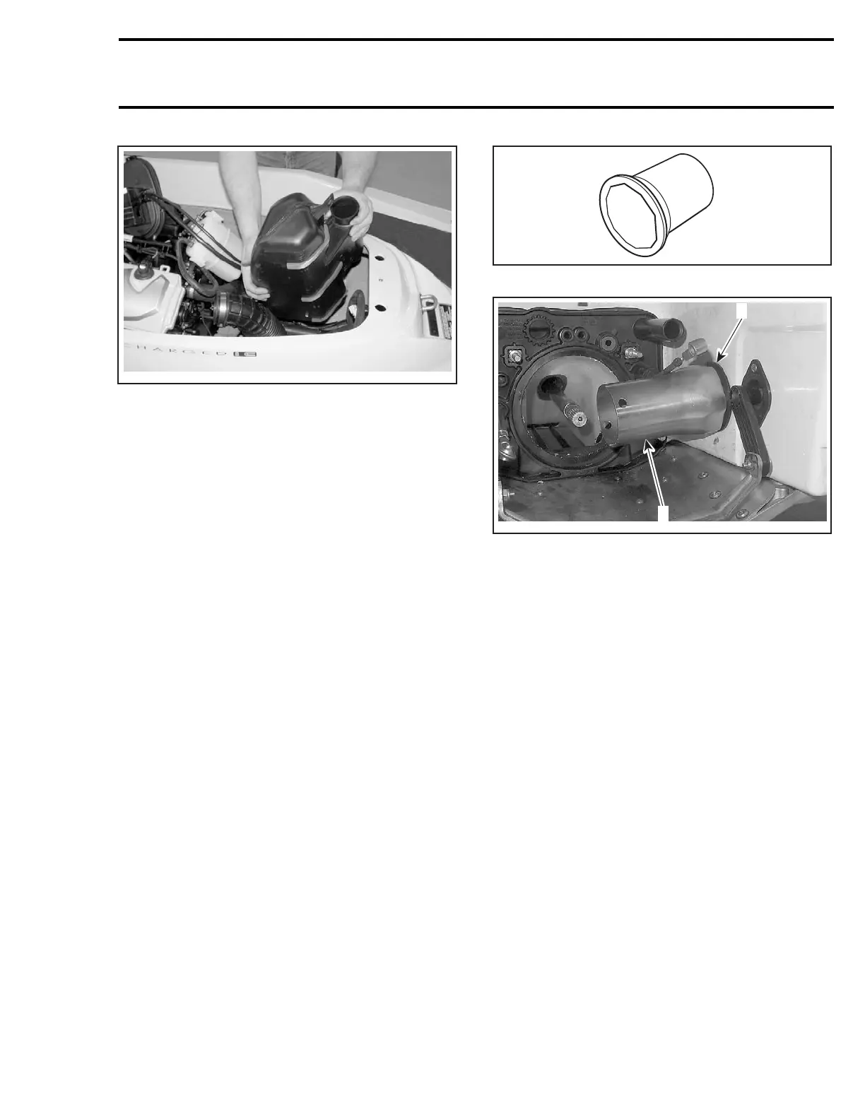
For resonator installation, remove hose no. 13
from exhaust outlet no. 11.
Install hose on resonator.
Install resonator in position while inserting hose
no. 13 on exhaust outlet.
All 4-TEC Models
After installation, ensure there is no coolant or ex-
haust gas leak when the engine is running. Test
run the engine while supplying water to the flush-
ing connector.
EXHAUST OUTLET
Removal
Remove resonator retaining screw no. 12.Move
resonator forward and disconnect hose no. 13
from exhaust outlet no. 11.
Remove the jet pump as an assembly from pump
support. Refer to PROPULSION SYSTEM.
From outside of hull, unscrew nut no. 10 with the
exhaust outlet tool (P/N 295 000 132).
F01B2AA
TYPICAL
F19D05A
1
2
TYPICAL
1. Exhaust outlet nut
2. Tool
From inside the bilge, remove exhaust outlet.
Inspection
Inspect parts condition paying attention for cracks
or other damage. Check hose. Replace any de-
fective part.
Installation
Installation is essentially the reverse of the re-
moval procedures. However, pay particular atten-
tion to the following.
Apply Loctite silicone sealant (P/N 293 800 086)
on the adapter flange to seal the bilge.
Test the bilge for water leaks.
smr2004-Complete Line Up 215

 Loading...


