Section 04 ENGINE (2-STROKE)
Subsection 06 (ROTARY VALVE)
Reinstall cover in place WITHOUT its O-ring and
torque screws to 20 N•m(15lbf•ft).
Remove cover then clean and measure com-
pressed soldering wire thickness, it must be
within the specified tolerance 0.30 ± 0.05 mm
(.012 ± .002 in).
If rotary valve cover clearance is over specified tol-
erances, machine rotary valve cover seating sur-
face or replace the cover.
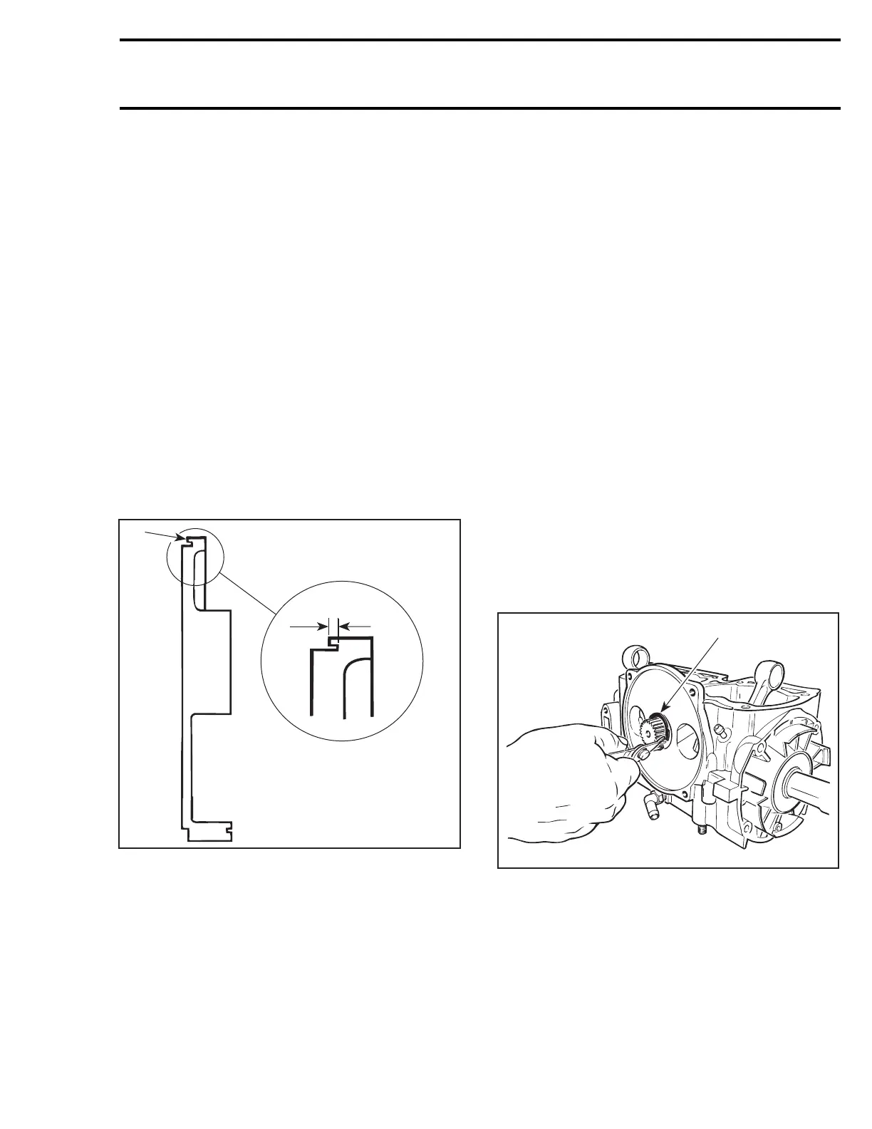
MACHINING INFORMATION
The amount of material over tolerance must be
removed from the rotary valve cover seating sur-
face.
Also cut the O-ring groove the same amount to
keep the 1.00 ± 0.03 mm (.039 ± .001 in) depth
between the bottom of the groove and the seating
surface.
Remove burrs on the edges of the seating surface
andO-ringgroove.
1
A
F01D3OA
SAME AMOUNT REMOVED FROM COVER SEATING
SURFACE AND O-RING GROOVE BASE
1. Cover seating surface
A. O-ring groove depth must be 1.00 ± 0.03 mm (.039 ± .001 in)
Reverify the clearance.
At assembly the rotary valve timing must remain
as per original setting.
NOTE: If rotary valve crankcase surface is worn, it
is possible to have it reworked at the factory.
Rotary Valve Shaft Gear Backlash
Remove PTO flywheel guard.
Remove spark plugs, rotary valve cover and valve.
Manually feel backlash at one position, then turn
crankshaft about 1/8 turn and recheck. Continue
this way to complete one revolution.
Backlash must be even at all positions. Otherwise
overhaul engine to find which part is faulty (gear,
rotary valve shaft or crankshaft with excessive de-
flection).
DISASSEMBLY
Rotary Valve Cover
Unscrew 4 retaining screws and withdraw rotary
valve cover no. 1 and rotary valve no. 13.
Rotary Valve Shaft
To remove the rotary valve shaft assembly, the
engine must be removed from watercraft (refer to
ENGINE).
Open bottom end and remove crankshaft (refer to
BOTTOM END).
First remove snap ring no. 4 from crankcase.
F01D22A
1
1. Removing snap ring
To remove rotary valve shaft assembly, use the
appropriate puller (P/N 290 876 488).
smr2004-Complete Line Up 155

 Loading...


