Section 12 ELECTRICAL SYSTEM
Subsection 03 (STARTING SYSTEM)
F01H0UA
2
1
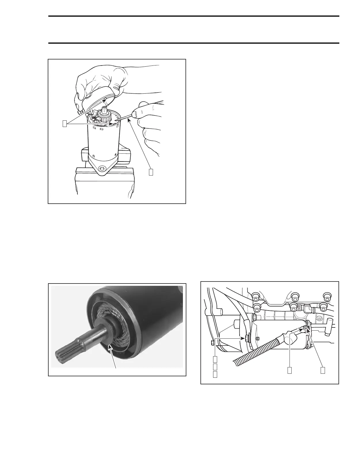
Step 1: Retaining brush holder with a screwdriver
Step 2: Align here
Align end frame notch with brush holder notch/
yoke protrusion.
CAUTION: Make sure end frame fits perfectly
on yoke.
947 DI Engines
Install new O-rings and gaskets.
Insert thrust washers no. 19 onto armature shaft.
F06H1HA
1
1. Thrust washers
Install the three washers no. 8 onto armature
shaft.
When installing end covers no. 3 and no. 10 to
yoke, align index marks.
Apply Loctite 271 (red) on through bolts no. 5 and
torque to 6 N•m(53lbf•in).
STARTER INSTALLATION
Installation is essentially the reverse of removal
procedure. However, pay particular attention to
the following.
Make sure that starter and engine mating surfaces
are free of debris. Serious trouble may arise if
starter is not properly aligned.
717 and 787 RFI Engines
Screw
Apply service products as per the exploded view
given at the beginning of the section, on threads
and torque starter screws no. 13 and no. 16 to
22 N•m(16lbf•ft).
Nut
Connect the RED positive cable to the starter and
torque nut no. 17 to6N•m(53lbf•in). Apply
dielectric grease on terminal and nut.
Screw and Teeth Washer
Apply Loctite 271 (red) to screw.
Connect BLACK negative cable to starter using flat
washer, teeth washer no. 15 and screw no. 14.
Torque screw to 22 N•m(16lbf•ft). Apply dielec-
tric grease on terminal and screw.
F01H1JC
1 4
2
3
4
717 ENGINES SHOWN
STEP 1: Torque nut to 6 N•m(53lbf•in)
STEP 2: Apply Loctite 271 on screw
STEP 3: Torque screw to 22 N•m(16lbf•ft)
STEP 4: Apply dielectric grease
smr2004-Complete Line Up 587

 Loading...


