Section 07 ENGINE MANAGEMENT (DI)
Subsection 02 (COMPONENT INSPECTION AND ADJUSTMENT)
Resistance Measurement
When measuring the resistance with an ohmme-
ter, all values are given for a temperature of 20°C
(69°F). The value of a resistance varies with the
temperature. The resistance value for usual re-
sistor or windings (such as injectors) increases
as the temperature increases. However, our tem-
perature sensors are NTC types (Negative Tem-
perature Coefficient) and work the opposite which
means that the resistance value decreases as the
temperature increases. Take it into account when
measuring at temperatures different from 20°C
(69°F). Use this table for resistance variation rel-
ative to temperature for temperature sensors.
TEMPERATURE RESISTANCE (OHMS)
°C °F NOMINAL LOW HIGH
-30 -22 12600 11800 13400
-20
-4
11400 11000 11800
-10
14
9500 8000 11,000
0 32 5900 4900 6900
10 50 3800 3100 4500
20 68 2500 2200 2800
30 86 1700 1500 1900
40 104 1200 1080 1320
50 122 840 750 930
60 140 630 510 750
70 158 440 370 510
80 176 325 280 370
90 194 245 210 280
100 212 195 160 210
110 230
145
125 160
120 248 115 100 125
CONVERSION CHART FOR TEMPERATURE SENSORS
The resista
nce value of a temperature sensor may
test goo
d at a certain temperature but it might be
defec
tive at other temperatures. If in doubt, try a
ne
wsensor.
Also remember this validates the operation of the
sensor at ambient temperature. It does not val-
idate the over temperature functionality. To test
it, the sensor could be removed from the engine/
muffler and heated with a heat gun while it is still
connected to the harness to see if the MPEM will
detect the high temperature condition and gener-
ate a fault code.
When working with injectors, the resistance value
might test good while the complete current would
not flow through the wire when pulsating current
is supplied to the injector in its normal operation.
A solution would be to use a jumper wire to direct-
ly supply the injector from the MPEM. If it now
works, replace the defective wire. A Noid light
(available from after-market tool/equipment sup-
pliers) may also be used to validate the injector
operation.
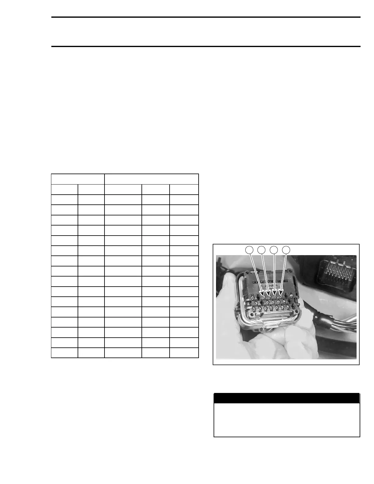
AMP CONNECTOR PIN-OUT
Use this diagram to locate the terminal numbers
on the AMP connector no. 3 and no. 4 of the
wiring harness when performing tests.
F07F15A
18 19 20 21
AMP CONNECTOR PIN-OUT (WIRING HARNESS SIDE)
QUICK FUEL PRESSURE TEST
WARNING
Read PRESSURE TEST under AIR/FUEL RAIL
further in this section for precautions and set-
up to take care of, before performing this test.
The procedure here is a quick summary.
smr2004-Complete Line Up 337

 Loading...


