Section 07 ENGINE MANAGEMENT (DI)
Subsection 02 (COMPONENT INSPECTION AND ADJUSTMENT)
After performing the required resets, ensure to
clear all faults from the newly replaced MPEM.
Now, all faults must be inactive (except the Diag-
nostic Cap Missing fault).
Start the engine and increase engine speed above
5000RPMtobesurenofaultappears.
THROTTLE POSITION SENSOR
(TPS)
General
The throttle position sensor (TPS) is a potentiome-
ter that sends a signal to the MPEM which is pro-
portional to the throttle shaft angle. On the DI sys-
tem, two sensors are used for redundancy purpos-
es. The MPEM compares the signals from both
sensors and determines if there is an error and
uses the most appropriate sensor to operate the
system.
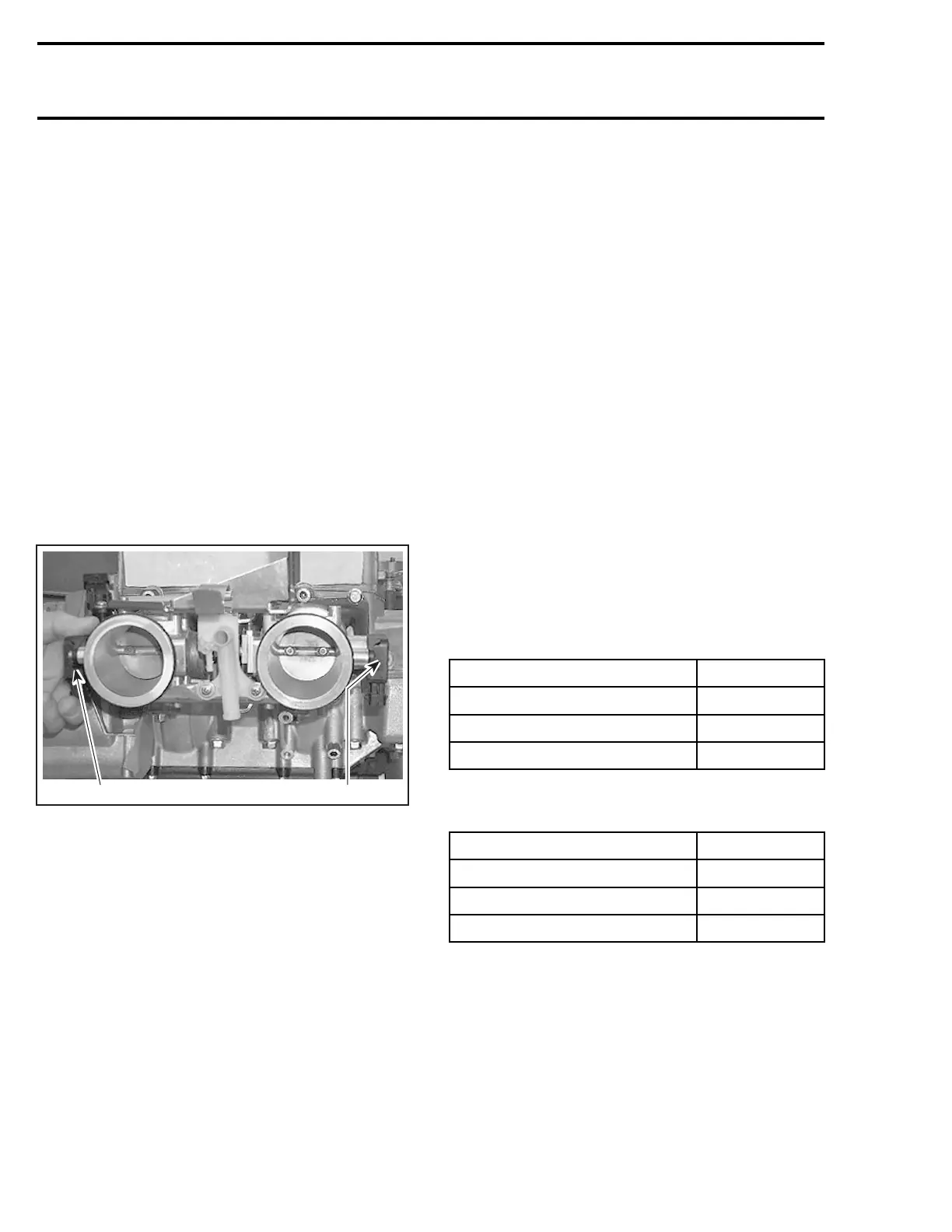
1
F12F05A
1
1. Throttle position sensor (TPS)
IMPORTANT: Prior to testing the TPS, ensure
that mechanical components/adjustments are
adequate according to THROTTLE BODY in AIR
INDUCTION SYSTEM above.
The MPEM may generate two types of fault codes
pertaining to the TPS. Refer to DI SYSTEM FAULT
CODES in DIAGNOSTIC PROCEDURES section
for more information.
Wear Test
While engine is not running, activate throttle and
pay attention for smooth operation without physi-
cal stops of the cable.
Using the vehicle communication kit (VCK) with
the B.U.D.S. software, use the Throttle Opening
display under Monitoring.
Slowly and regularly depress the throttle. Ob-
serve the needle movement. It must change
gradually and regularly as you move the throttle.
If the needle “sticks”, bounces, suddenly drops
or if any discrepancy between the throttle move-
ment and the needle movement is noticed, it
indicates a worn TPS that needs to be replaced.
NOTE: In this particular case, by comparing the
signals from both sensors, the MPEM will gener-
ate a fault code when the TPS is malfunctioning
due to specific “spots”.
To isolate the faulty TPS, disconnect one and test
the other.
Voltage Test — Both TPS
Check the MPEM voltage output on the desired
throttle position sensor.
Disconnect connector from throttle position sen-
sor and connect a voltmeter to the wiring harness.
Check the voltage readings on the PTO side as
follows.
CONNECTION VOLTAGE
Terminal 1 with engine ground 5V
Terminal 2 with engine ground 0V
Terminal 3 with engine ground 0-0.5V
Check the voltage readings on the MAG side as
follows.
CONNECTION VOLTAGE
Terminal 1 with engine ground 5V
Terminal 2 with engine ground 0V
Terminal 3 with engine ground 4.75 - 5 V
If voltage test is good, replace the TPS.
If voltage test is not good, check the resistance of
the TPS circuit.
Resistance Test
Reconnect the TPS.
358 smr2004-Complete Line Up

 Loading...


