Section 16 HULL/BODY
Subsection 01 (ADJUSTMENT AND REPAIR)
F07L0AA
1
TYPICAL
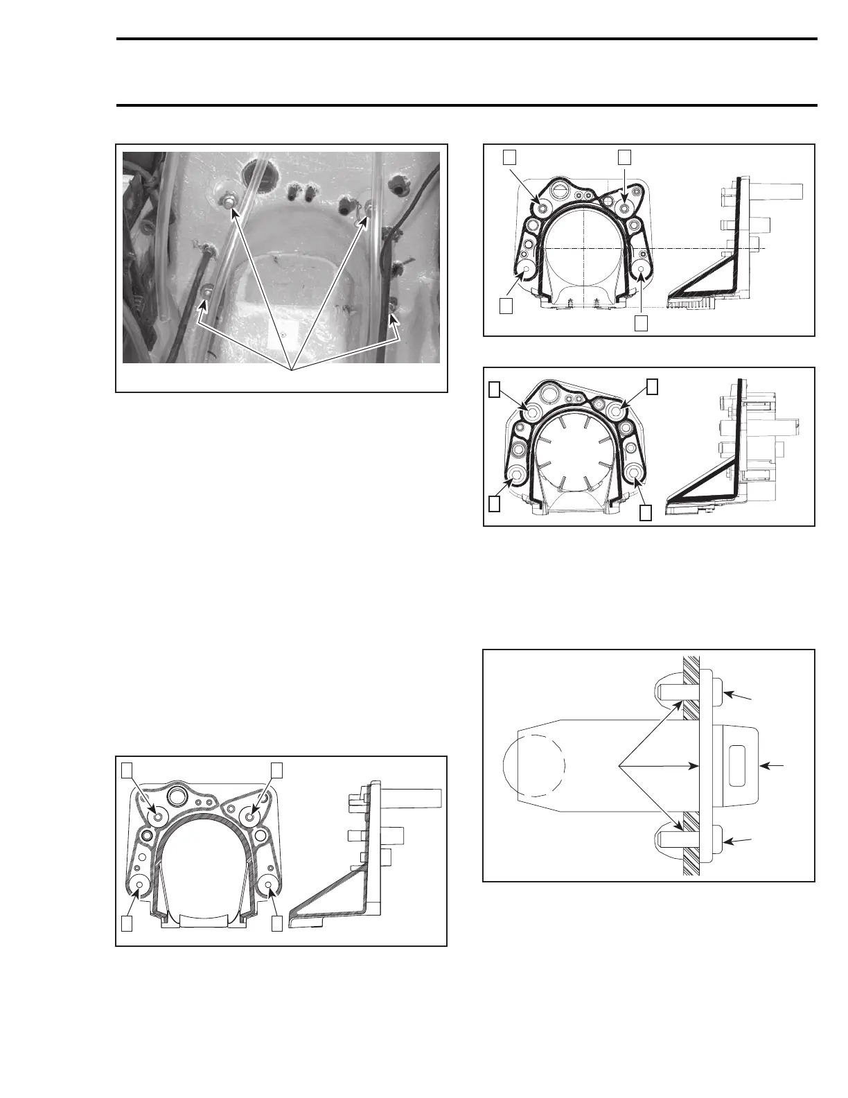
1. Remove nuts
Using a heat gun, heat jet pump support until it is
possible to pull it.
NOTE: Shims may have been installed between
support and body. Do not remove these shims,
otherwise jet pump alignment will be altered.
Installation
All Models except RXP 4-TEC
Ensure to position the longest threaded portion of
studs towards the jet pump. Apply Loctite 518
(P/N 293 800 038) against contact surface of studs
with jet pump support.
All Models
Apply Loctite 5900 (P/N 293 800 066) as indicated
by the shaded areas in the next illustrations. Fol-
low also the torquing sequence as shown in the
same illustrations. Torque to 31 N•m(23lbf•ft).
4
21
F08L1OA
3
GTI SERIES AND XP DI MODELS
F18L28A
4
3
1 2
GTX 4-TEC SERIES
F19J0AA
1
2
3
4
RXP 4-TEC MODELS
DRAIN PLUG INSTALLATION
Refer to the following illustration to install drain
plug no. 15.
2
F00L2RA
3
3
1
1. Drain plug
2. Silicone sealant (P/N 293 800 086) around the middle
hole and in the screw holes
3. Torque screws to 2.2 N•m(19lbf•
in)
smr2004-Complete Line Up 751
 Loading...


