Section 07 ENGINE MANAGEMENT (DI)
Subsection 02 (COMPONENT INSPECTION AND ADJUSTMENT)
Gently pull rail up by hand, working each side
slightly at a time.
Pull rail out.
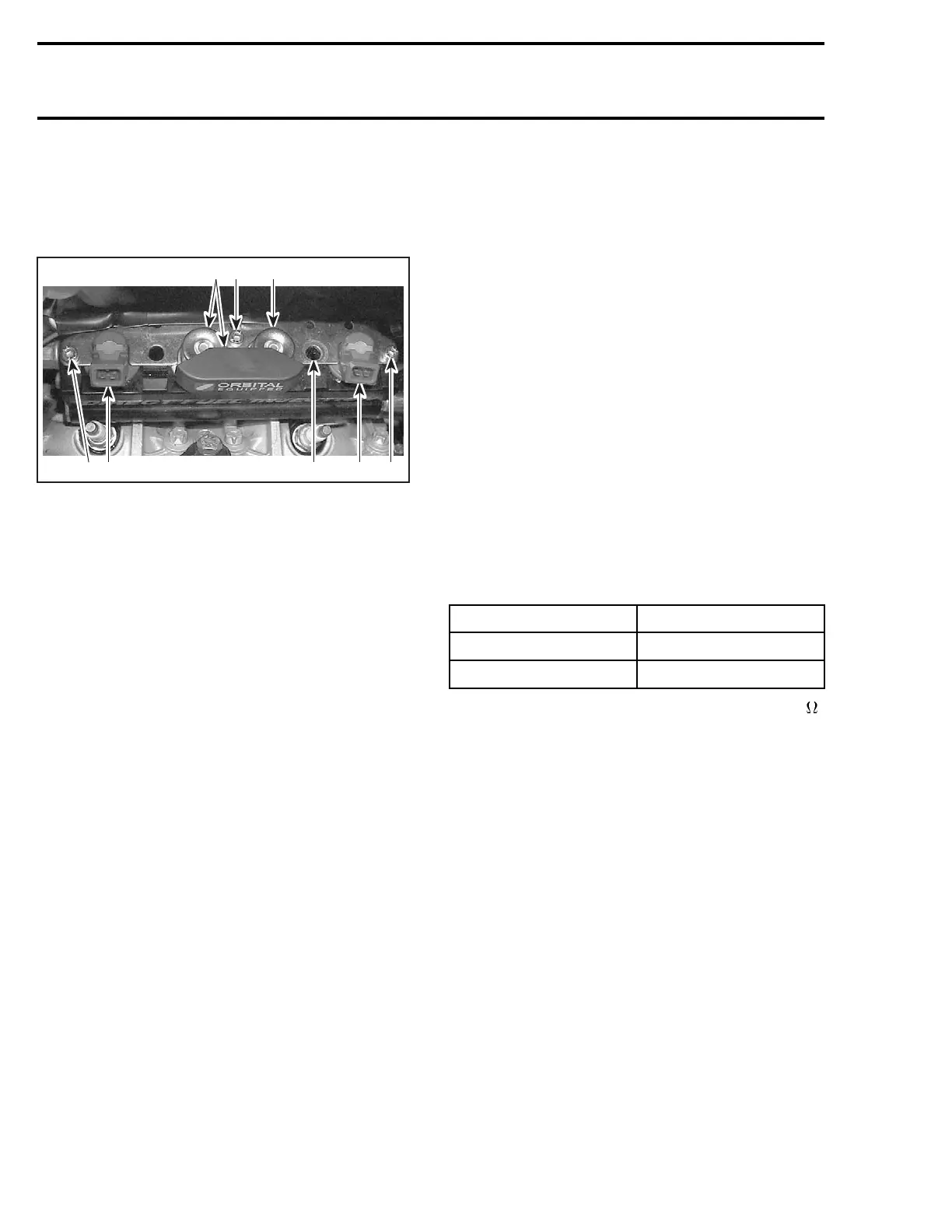
Unscrew retaining plate screws.
4
2
F12R1AA
3 132
25
1. Retaining plate
2. Screws
3. Fuel injector
4. Fuel pressure regulator and cover
5. Air pressure regulator
NOTE: If needed, use a small screwdriver to lift
the fuel pressure regulator.
To remove fuel pressure regulator, pull the fuel
regulator and the cover out of rail.
Installation
For the installation, reverse the removal procedure
but pay attention to the following.
If the same regulator is reinstalled, it is recom-
mended to change the O-rings.
Insert the fuel pressure regulator into the cover
then install both regulators together in place with
your hand. Do not use any tool.
NOTE: A thin film of injection oil may be applied
on O-ring to ease insertion in rail.
Apply Loctite 243 on rail retaining screws then
torque to 25 N•m(18lbf•ft).
FUEL INJECTOR
Leakage Test
Testing the fuel injector operation can be per-
formed with the air/fuel rail installed.
The leakage test is validated when performing the
FUEL DELIVERY SYSTEM DIAGNOSTIC FLOW
CHART elsewhere in this section.
Electrical Test
SafetylanyardmustbeonDESSpost.
Using the vehicle communication kit (VCK) with
the B.U.D.S. software, energize the fuel injector
from the Activation tab.
If the injector does not work, disconnect the con-
nector from the injector.
Install a temporary connector to the injector with
wires long enough to make the connection out-
side the bilge and apply voltage (12 V) to this test
harness.
This will validate the injector mechanical and elec-
trical operation.
If it does not work, replace it.
Otherwise, check the resistance of the fuel injec-
tor circuit.
Reconnect the injector and disconnect the AMP
connector number 4 on the MPEM.
Using a multimeter, check resistance value be-
tween terminals as follows.
COMPONENT TERMINAL LOCATION
Fuel injector MAG
7 and 13
Fuel injector PTO
8 and 14
The resistance should be between 1.7 and 1.9 .
If resistance value is correct, try a new MPEM.
Refer to MPEM REPLACEMENT procedures else-
whereinthissection.
If resistance value is incorrect, repair the wiring
harness/connectors between AMP connector and
fuel injector.
Fuel Injector Replacement
When any fuel injector is defective, while replac-
ing it, make sure to check the other one as well.
Also check direct injectors. Replace if defective.
Removal
See FUEL PRESSURE REGULATOR REPLACE-
MENT above for procedure. However, do not
remove any regulator.
To remove fuel injector, pull it out of rail.
Installation
For the installation, reverse the removal proce-
dure. Paying attention to the following details.
348 smr2004-Complete Line Up

 Loading...


