Section13PROPULSION
Subsection 04 (VARIABLE TRIM SYSTEM)
GENERAL
To test VTS control module, motor or switch, refer
to INSTRUMENTS AND ACCESSORIES.
To have access to VTS module, remove seat and
engine cover on RXP models and remove rear ac-
cess cover on XP DI.
REMOVAL
All Models
Remove nut no. 14 and bolt no. 13 retaining VTS
rod no. 1 to sliding shaft no. 10.
Remove clamps no. 2.
Remove boot no. 3.
1
F16J0AA
3
4
2
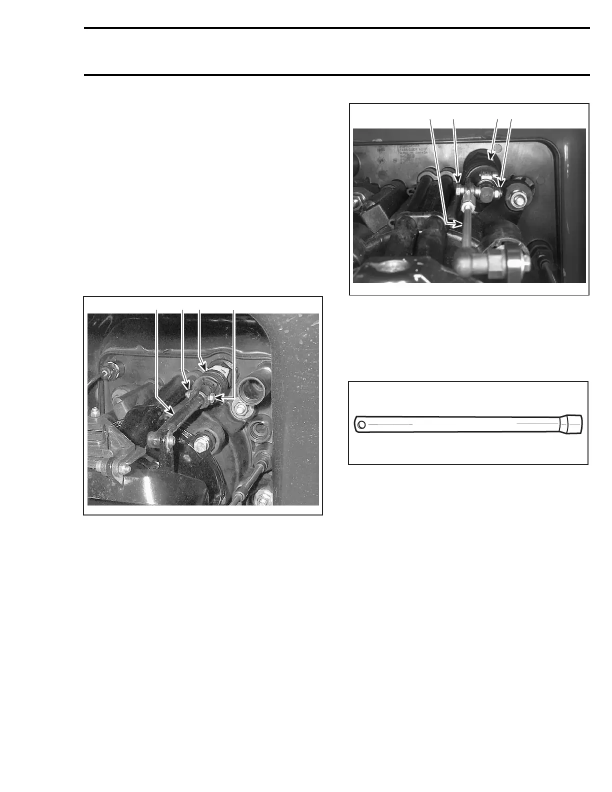
RXP MODELS
1. VTS rod
2. Bolt
3. Lock nut
4. Rubber boot
F06J01E
1
2
3
4
XP DI MODELS
1. VTS rod
2. Bolt
3. Lock nut
4. Rubber boot
To loosen nut no. 4, use VTS socket tool (P/N 295
000 133).
F01B2PA
Remove sealing washer no. 5.
All Models
Disconnect wiring harnesses.
Pull out VTS assembly no. 6 from bilge.
DISASSEMBLY
Cover
Remove VTS cover no. 7 by pressing on tabs.
smr2004-Complete Line Up 681

 Loading...


