Section 04 ENGINE (2-STROKE)
Subsection 04 (TOP END)
947 DI Engines
Due to the semi-trapez rings, it is not possible to
accurately measure ring/piston groove clearance.
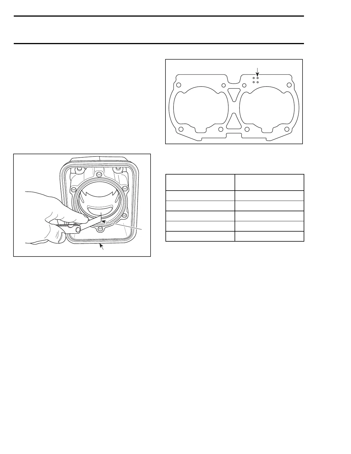
Ring End Gap
Position ring halfway between exhaust port and
top of cylinder.
NOTE: In order to correctly position ring in cylin-
der, use piston as a pusher.
Using a feeler gauge, check ring end gap. If gap
exceeds specified tolerance, rings should be re-
placed.
F01D0OA
1
2
1. Top of cylinder
2. Ring end gap
Cylinder Base Gasket
NOTE: The general procedure is to install a new
gasket of the same thickness. However, if you
do not know the gasket thickness that was in-
stalled or if a crank repair has involved replace-
ment of connecting rods, refer to the COMBUS-
TION CHAMBER VOLUME MEASUREMENT to
properly determine the required gasket thickness.
Different thicknesses of cylinder base gaskets are
used for a precise adjustment of the combustion
chamber volume.
To identify gasket thickness, refer to the identifi-
cation holes on the gasket.
F01D67A
1
TYPICAL
1. Identification holes
All Engines
GASKET THICKNESS
IDENTIFICATION
HOLES
0.3 mm (.012 in) 3
0.4 mm (.016 in) 4
0.5 mm (.020 in)
5
0.6 mm (.024 in) 6
0.8 mm (.031 in) 8
RAVE Valve
787 RFI and 947 DI Engines
Check RAVE valve bellows no. 21 for cracks.
ASSEMBLY
Assembly is essentially the reverse of disassem-
bly procedures. However pay particular attention
to the following.
RAVE Valve
787 RFI Engines
Make sure to insert O-ring no. 23 onto rod of slid-
ing valve no. 22.
The TOP position of the sliding valve no. 22 is
indicated on one side.
116 smr2004-Complete Line Up

 Loading...


