Section10FUELSYSTEM
Subsection 01 (FUEL CIRCUIT)
NOTE: It is a one-way valve with an arrow to indi-
cate the air flow.
Check Valve
Check if the check valve no. 18 functions properly.
Black side of the one-way check valve is the valve
outlet. It allows air to get in reservoir.
Baffle Pick-Up Filter
Carburetor-Equipped Models
Inspect filter no. 12 of baffle pick-up no. 8.Clean
or replace as necessary.
Fuel Tank
All Models
Visually inspect the inside and outside of the fuel
tank necks for crack(s). If crack(s) are existing,
replace fuel tank no. 6.
Check with your finger to feel the inside and out-
side surfaces of fuel tank. Flex fuel tank necks to
ensure there are no hidden cracks.
F07F06A
4
2
1
A
3
5
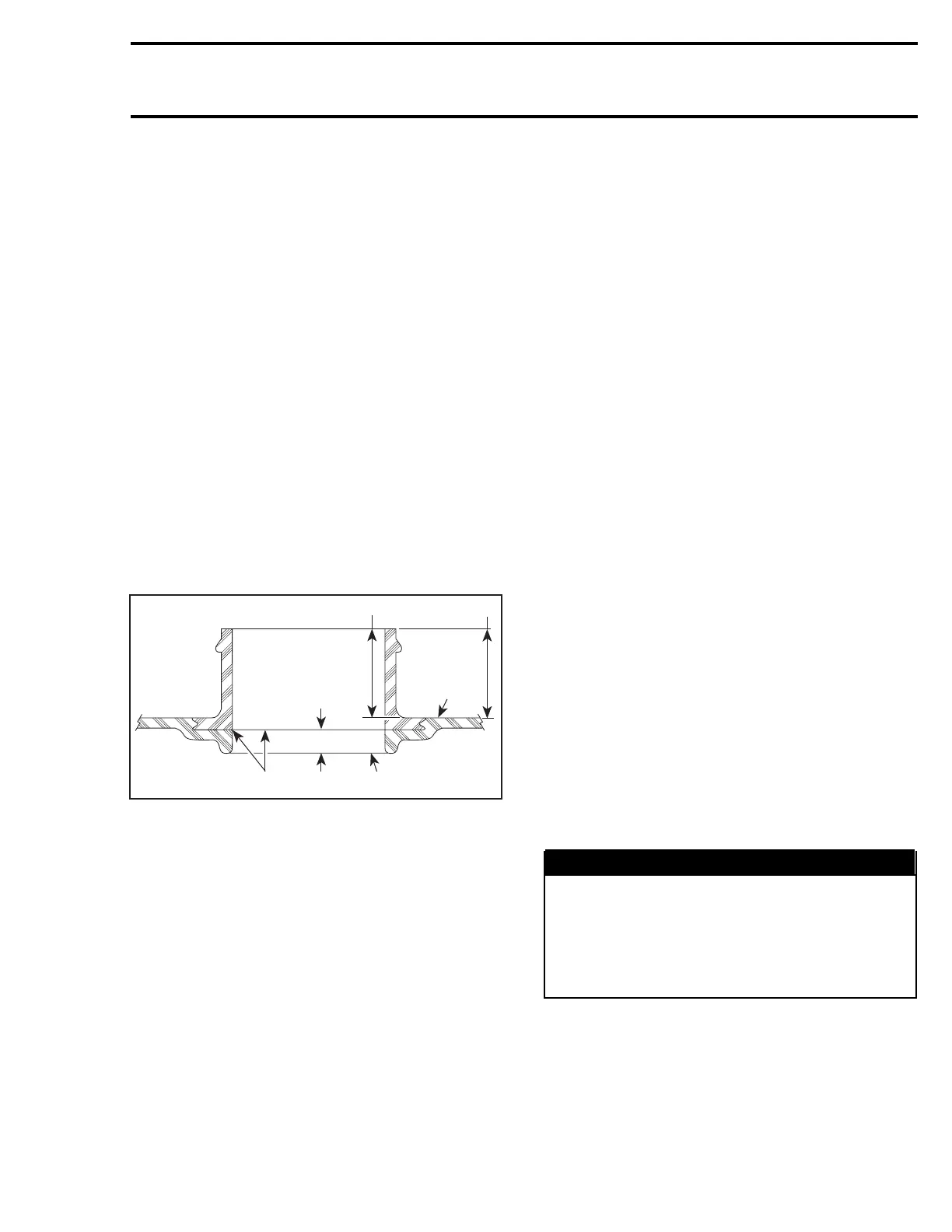
1. Tank upper surface
2. Inspect outside, above upper surface
3. Normal molding seam
4. Inspect inside, above upper surface
5. Base of the neck
A. Approx. 4 mm (5/32 in)
NOTE: A fuel tank is comprised of 3 components:
the tank, the fuel pick-up neck and the filler neck.
The necks are injection molded and the tank is
then blow molded over the necks. During the
molding process, a small molding seam may ap-
pear on the inner side of the necks at approximate-
ly 4 mm (5/32 in) from the base of the neck. It is
a normal situation to have a molding seam and it
should not be confused with a crack.
ASSEMBLY
Assembly is essentially the reverse of disassem-
bly procedures. However pay particular attention
to the following.
Fuel Tank
Ensure rubber carpets no. 19 are in place.
All Models except 4-TEC
Insert fuel tank in the vehicle and place straps in
bottomclips. Usetapetoholdstrapsonthetop
of fuel tank.
4-TEC Engines
Insert tank, air box and straps.
Place straps in clips (bottom) and in guides of air
box. Usetapetoholdstrapsonthetopoffuel
tank.
All Models
Insert strap ends in hoops.
Properly secure harnesses.
Reinstall all other removed parts. Refer to the ap-
propriate section.
Baffle Pick-Up
Carburetor-Equipped Models
Slide adapter no. 11 onto baffle pick-up no. 8 until
it stops on rib. Install clamp no. 10.
Install baffle pick-up no. 8 into fuel tank and push
it until it sits on fuel tank neck. Install clamp no. 9
and torque both clamps to 3 N•m(27lbf•in).
FUEL SYSTEM PRESSURIZATION
WARNING
Whenever doing any type of repair on wa-
tercraft or if any components of the fuel sys-
tem are disconnected, a pressure test must be
done before starting engine. Ensure to verify
fuel line ends for damage. Always cut dam-
aged end before reinstallation.
smr2004-Complete Line Up 509

 Loading...


