Section 18 WIRING DIAGRAM
Subsection 01 (WIRING DIAGRAMS)
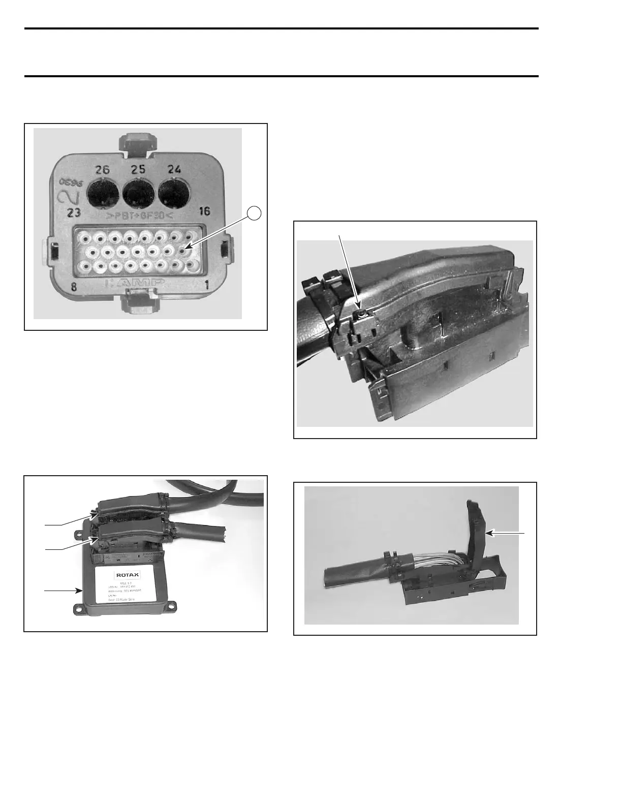
AMP Connectors of Wiring Harness
F04H6GA
9
ECM CONNECTORS
4-TEC Models Only
There are two ECM connectors used on the 4-TEC
models and they are connected on the ECM. The
engine harness female connector is connected on
the module male connector “A” and the water-
craft system control harness female connector is
connected to the module male connector “B”.
The engine connector has 41 pins.
1
F18Z02A
2
3
1. ECM
2. A connector (engine harness)
3. B connector (watercraft system harness)
CAUTION: Do not disconnect the ECM connec-
tors needlessly. They are not designed to be
disconnected/reconnected frequently.
CAUTION: Probe on top of terminal only. Do
not try to probe inside terminal or to use a pa-
per clip to probe inside terminal, it can damage
the square-shaped terminal.
Terminal Removal
Unlock the connector cover by pushing in the tabs
on top of the connector with a flat screwdriver to
be able to flip the top cover up.
1
F18Z0RA
1. Push in tab
Lift the cover by pushing it forward.
1
F18Z06A
1. Cover
Cut both tie raps that secure the harness to the
connector.
794 smr2004-Complete Line Up

 Loading...


