Section 18 WIRING DIAGRAM
Subsection 01 (WIRING DIAGRAMS)
1
F18Z07A
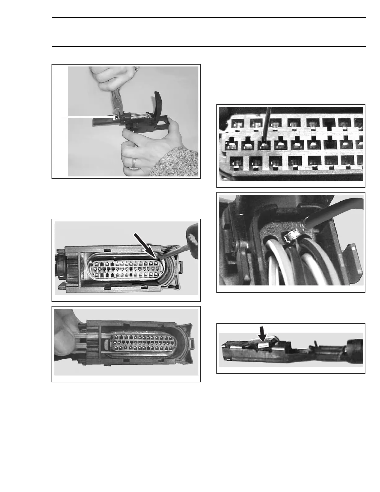
1. Tie raps
Turn the connector over and remove the orange
locking tab by pushing and then pulling toward the
wire harness.
F18Z0SA
F18Z0TA
A terminal remover such as Snap-On TT600-1 (or
a 0.76 mm (.030 in) oxyacetylene torch tip cleaner
or a #68 drill bit) must be inserted into the terminal
cavity to release the locking tab from the connec-
tor.
CAUTION: Using a tool tip larger than 0.76 mm
(.030in)maydamagetheterminal.
Insert the tool tip into the terminal cavity as
shown, and locate its wire in the back of the con-
nector. You may have to pry the tool tip against
thelockingtabtoreleaseit,thenremovethe
terminal from the connector.
F18Z0UA
F18Z0VA
Check the locking tab on the terminal, it may have
to be bent out a little so it will lock in its cavity
when it is re-inserted.
F18Z0WA
Ifthewireisingoodconditionbuttheterminal
is rusted or corroded, remove defective terminal
and crimp a new one. If wire and terminal are de-
fective, replace with a new genuine wire and new
terminal and crimp them together as explained be-
low.
IMPORTANT: Use genuine wires only. Otherwise
wires will not fit properly.
smr2004-Complete Line Up 795

 Loading...


