Section 09 COOLING SYSTEM
Subsection 01 (CIRCUIT, COMPONENTS AND CARE)
CIRCUIT
Closed Loop System
A closed loop cooling system is utilized on the
1503 4-TEC engines, which offers an efficient en-
gine cooling while keeping dirt and salt water out
of the cooling system. This system keeps the
temperature constant and prevents internal en-
gine corrosion.
A separate coolant expansion tank ensures that
enough engine coolant is in the circuit during any
operating condition.
The coolant flow comes from the coolant pump
impeller into the engine block. It goes around the
cylinders and straight up to the cylinder head. A
smaller quantity of engine coolant enters the en-
gine block on the exhaust side for a better cool-
ing. In the cylinder head the water channels flow
around the exhaust and then the intake valves and
leave the engine through a large hose. From there
the coolant goes back to the coolant pump hous-
ing and depending on the engine temperature, it
flows through the thermostat directly back to the
coolant pump impeller, or it takes its way through
the ride plate which operates as a heat exchanger.
A smaller quantity of engine coolant is also direct-
ed towards the oil cooler, which is located under
the air intake manifold, to increase cooling effi-
ciency.
Coolant temperature sensor and bleed nipple are
located on the cylinder head.
1
F18E0XA
2
1. Bleed nipple
2. Coolant temperature sensor (CTS)
CAUTION: Never modify cooling system ar-
rangement, otherwise serious engine damage
could occur.
Pressure Cap
Check if cap pressurize the system. if not, install
a new 90 kPa (13 PSI) cap (do not exceed this
pressure).
COOLING SYSTEM LEAK TEST
WARNING
To prevent burning yourself, do not remove
the expansion tank cap or loosen the ride-
plate drain plug if the engine is hot.
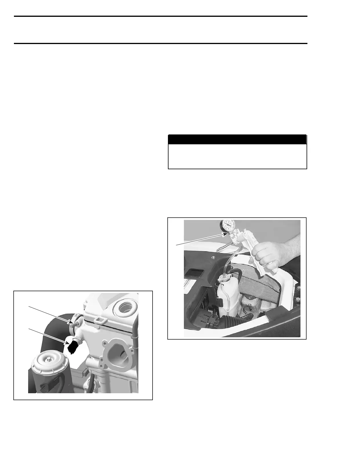
Install test radiator cap (P/N 529 021 991).
NOTE: It is not necessary to install a hose pincher
on overflow hose.
Pressurize all system through coolant expansion
tank to 90 kPa (13 PSI).
1
F18E25A
1. Pressure pump (P/N 529 021 800)
Check all hoses, ride plate, engine and oil cooler
for coolant leaks. Spray a soap/water solution and
look for air bubbles.
Remove hose pincher and test pressure cap.
Open Loop System
The water supply is provided by a pressurized area
in the jet pump between the impeller and venturi.
488 smr2004-Complete Line Up

 Loading...


