Section 05 ENGINE (4-TEC)
Subsection 05 (PTO HOUSING/MAGNETO)
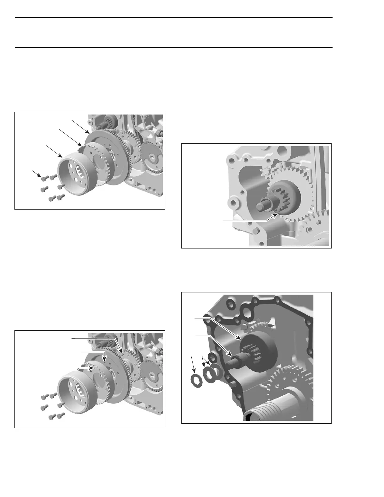
Remove:
– PTO housing cover
– hexagonal screws no. 18.
Withdraw rotor no. 19, encoder wheel no. 20 and
starter ring no. 21.
1
R1503motr54A
2
3
4
TYPICAL
1. Hexagonal screws
2. Rotor
3. Encoder wheel
4. Ring gear
Inspection
Check ring gear condition, especially teeth condi-
tion. If damaged, replace faulty part.
Installation
For installation, reverse the removal procedure.
However, pay attention to the following.
Ring gear and encoder wheel position has to be lo-
cated with the location pin on the crankshaft gear.
1
R1503motr54B
2
TYPICAL
1. Location pin
2. Location pin holes
Apply Loctite 243 on threads. Torque rotor screws
to 24 N•m(17lbf•ft).
STARTER DRIVE ASS'Y
Removal
Remove:
– PTO housing and ring gear as described above
– starter drive ass'y no. 8.
1
R1503motr55A
TYPICAL
1. Starter drive ass'y
CAUTION: Be careful not to lose the distance
washer, disc springs no. 6 and washer no. 7
located on the starter drive shaft.
R1503motr263A
21
3
4
TYPICAL
1. Disc springs
2. Washer
3. Flange washer
4. Starter drive gear
232 smr2004-Complete Line Up

 Loading...


