Section 05 ENGINE (4-TEC)
Subsection 08 (ENGINE BLOCK)
CRANKSHAFT AXIAL CLEARANCE mm (in)
NEW MINIMUM 0.08 (.003)
NEW MAXIMUM
0.22 (.009)
SERVICE LIMIT 0.35 (.014)
1
R1503motr42A
2
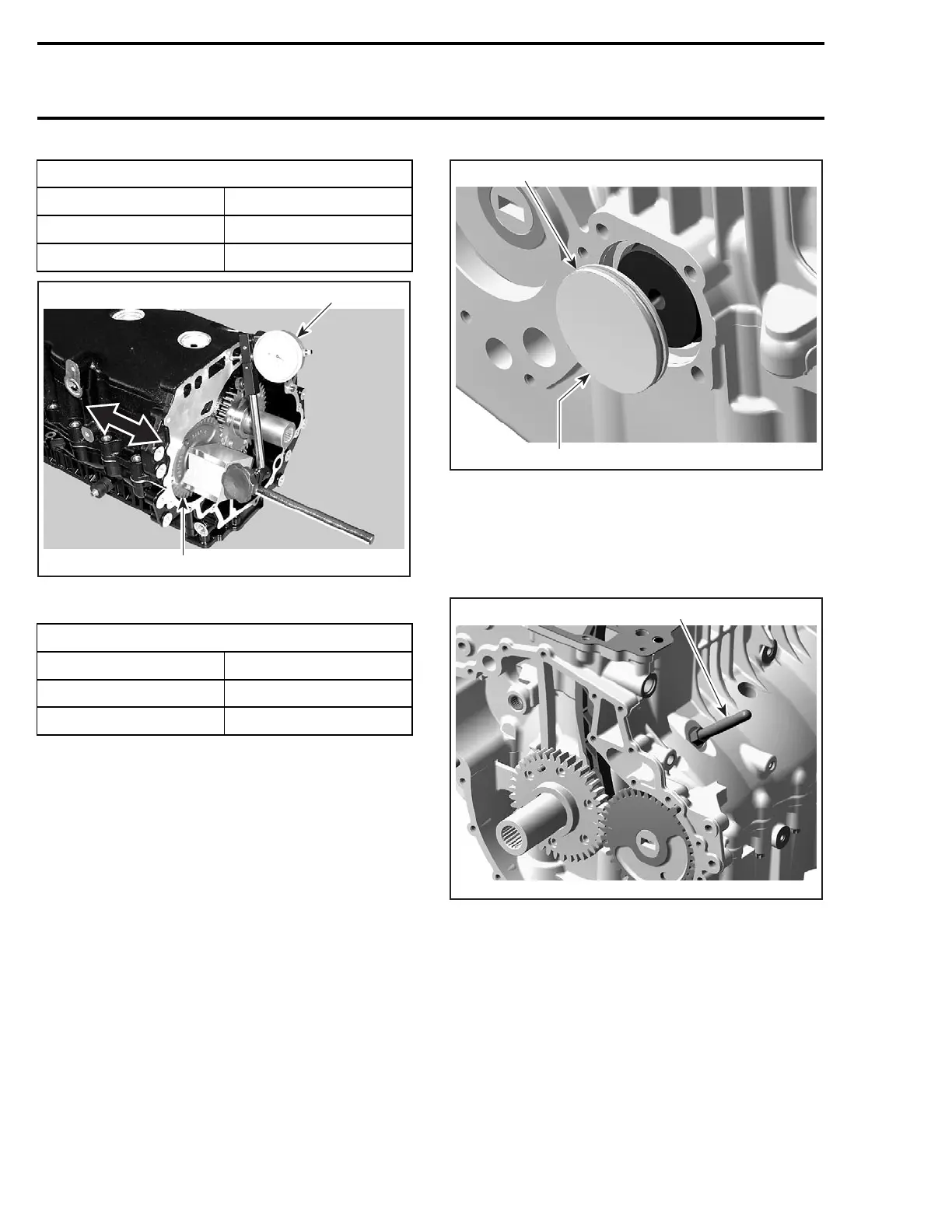
1. Dial gauge
2. Balancer shaft
BALANCER SHAFT AXIAL CLEARANCE mm (in)
NEW MINIMUM 0.02 (.001)
NEW MAXIMUM
0.25 (.010)
SERVICE LIMIT 0.35 (.014)
Install the crankshaft cover before mounting the
engine bracket. Apply oil on O-ring and press cov-
er in. Crankshaft cover has to be flush with engine
block surface.
1
R1503motr19A
2
1. O-ring
2. Crankshaft cover
CAUTION: Install crankshaft locking tool
(P/N 529 035 821) right away to position crank-
shaft at TDC before installing the camshaft and
rockers (refer to CYLINDER HEAD AND VALVE).
1
R1503motr18A
1. Crankshaft locking tool
Install cylinder head, PTO housing and the oth-
er parts in accordance with the proper installation
procedures.
PISTON/CONNECTING ROD
Removal
Disassemble engine block as per ENGINE BLOCK
REMOVAL above.
Remove connecting rod screws.
288 smr2004-Complete Line Up

 Loading...


