Section 18 WIRING DIAGRAM
Subsection 01 (WIRING DIAGRAMS)
WIRING DIAGRAMS
WIRE COLOR CODES
First color of a wire is the main color. Second color
is the tracer.
Example: YELLOW/BLACK (YL-BK) is a YELLOW
wire with a BLACK tracer.
WIRE DIGIT CODES
First number indicates in which connector the wire
is plugged in.
Second number indicates the position of the wire
in the connector.
Theletterattheendofthenumber(ifapplicable)
indicates a common circuit in the MPEM printed
circuit with another wire bearing the same letter.
Example: 2-18 (g)
The first number indicates that the wire is posi-
tioned in the connector no. 2 of the MPEM.
The second number indicates that the wire is po-
sitioned in cavity no. 18 of the connector.
The letter (g) indicates a common circuit with an-
other wire(s) bearing the same letter (g) in the cir-
cuit.
ECM
GTX 4-TEC Models
On the ECM, circuits are identified by a letter fol-
lowed by a number.
The letter indicates in which connector the wire is
plugged in.
The number indicates the position of the wire in
the connector.
The connector “A” is connected to the engine
wiring harness.
The connector “B” is connected to the watercraft
wiring harness.
DEUTSCH CONNECTORS
All Models
Deutsch connectors are used to connect wiring
harness to the magneto the electrical box (some
models) and the VCK (DI and 4-TEC models).
Removal from Engine Connector
Bracket
GTX 4-TEC Models
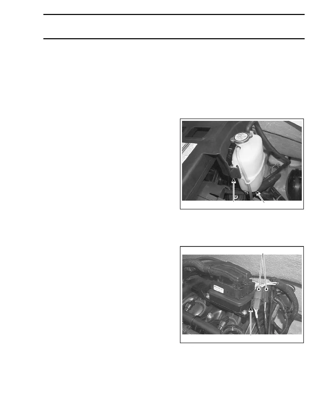
To remove Deutsch connectors from engine con-
nector bracket, remove the expansion coolant
tank.
1
F18Z0IA
2
1. Expansion coolant tank
2. Tank bracket
Slide a flat screwdriver between the connector
bracket and the Deutsch connectors and remove
connectors.
1
F18Z0JA
2
1. Engine connector bracket
2. Deutsch connectors
smr2004-Complete Line Up 787

 Loading...


